Our top-of-switch rack decides to die randomly from time to time. It was somewhat inconvenient since it also killed most of our infrastructure including primary and secondary DNS so I needed a solution quickly. Since different rack is still on the network, I should be able to hack something and finally connect my Arduino knowledge and sysadmin realm, right? Think of it as power cycle watchdog based on network state.
First thing was to figure out what was happening with the switch. It seemed like it was still working (LEDs did blink), but only thing that helped was power cycle. So as a first strep, I connected serial console (using RS-232 extension cable) to on-board serial port (since it doesn't seem to work using cheap CH340 based USB serial dongles) and I didn't expect this:
0x37491a0 (bcmCNTR.0): memPartAlloc: block too big 6184 bytes (0x10 aligned) in partition 0x30f6d88
0x3cd6bd0 (bcmCNTR.1): memPartAlloc: block too big 6184 bytes (0x10 aligned) in partition 0x30f6d88
0x6024c00 (simPts_task): memPartAlloc: block too big 1576 bytes (0x10 aligned) in partition 0x30f6d88
0x6024c00 (simPts_task): memPartAlloc: block too big 1576 bytes (0x10 aligned) in partition 0x30f6d88
When I google messages like this I get two types of answers:
- beginner questions about VxWorks which summ up to: you have memory leak
- errors from switches with boardcomm chipset from various vendors
Serial console did emit a lot of messages, but didn't respond to input at all. I would at last expect that watchdog timer in the switch will reset it once it manages to fragment it's own memory so much that it has stopped forwarding packets, oh well.... What else can I do?
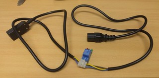
IEC power cable with relay
I wanted something what I can plug in between the existing switch with IEC power connector with USB on the other end that can be plugged into any USB port for control.
Since this is 220V project (and my first important one), I tried to do it as safe as possible.
- I started with a power cable, that I cut in half and put ferrules on all wires to be sure that connectors will grip those wires well.
- Then I replaced the power plug with IEC connector so it's can be inserted in any power cable. In this case, we soldered wires ends, since ferrules where too big to fit into connector housing. We did wrap a wire around a screw in a connector correctly, so tightening the screw will not displace the wire.
- Finally I connected cheap 10A 250VAC relay which should be enough for fully loaded 48 port gigabit network switch that draws round 80W.
- To make sure that rest of the system can't just power cycle device connected at any time, I connected live wire through normally closed pins on a relay. This means that this cable should work as-is (without powering it at all) and when powered, since board has pull-up resistor on the relay to VCC, the relay will be in the same sate, passing power to device.
- Finally I checked all three power cable wires with multi-meter and got around 0.2 ohms which mans that whole thing works for now.
Putting it into a box
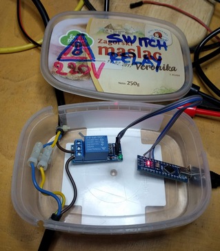
I really wanted to somehow fix wires and protect the bottom of the relay board (which has 220V on it) from shorting to something, so I used an old box from a dairy product and created a housing for electronics.
If you look carefully, you will notice that I had to cut the case all the way through to pass through the power
cable (that has a zip-tie on inside to prevent it from pulling out).
The Case will be fixed using hot glue and a lid, so this won't be a problem.
Warning and label on the lid is also nice touch, and shouldn't be skipped when creating a thing
which you won't be only user of.
Arduino software
You will also notice that relay is connected to A7, which didn't work out. Let me explain:
The idea is to use Arduino default pin state (INPUT) as a state in which the pin will stay most of the time.
This makes pin floating, and we can inspect pull-up on relay board and report if we see it.
When we want to activate the relay, we'll flip pin to output, pull it down, and activate the relay.
Code is available at
https://github.com/dpavlin/Arduino-projects/blob/nuc/power_cycle/power_cycle.ino
and it can't be much simpler:
/*
 * power cycle switch
 *
 * relay is connected across 5V relay through normally closed pins so that failure of arduino doesn't kill power to switch.
 * to activate relay on this board, signal pin has to be pulled to ground.and coil draw is 76 mA when active
 * board has pull up on input pin to it's vcc
*/

#define RELAY_PIN 2

void setup() {
  Serial.begin(115200);

  pinMode(LED_BUILTIN, OUTPUT);

  pinMode(RELAY_PIN, INPUT); // don't modify pin state
  Serial.print("Relay pin on reset: ");
  Serial.println(digitalRead(RELAY_PIN));
}

void loop() {
  if ( Serial.available() ) {
    char c = Serial.read();
    if ( c == '0' ) {
      Serial.print("L");
      pinMode(RELAY_PIN, OUTPUT);
      digitalWrite(RELAY_PIN, LOW); // activate relay

      digitalWrite(LED_BUILTIN, HIGH); // led on
    } else if ( c == '1' ) {
      Serial.print("H");
      pinMode(RELAY_PIN, INPUT);

      digitalWrite(LED_BUILTIN, LOW); // led off
    } else {
      Serial.print(c);
    }
  }
}
Simple is good: I toyed with idea of automatically releasing the relay from Arduino code, and when I
started to implement timeout configuration on Arduino side, I remembered what this will be plugged
into random server USB port, without avrdude and any handy way to update firmware on it,
so I decided to just leave simplest possible commands:
- 1 - ON (outputs H) - power on, default
- 0 - OFF (outputs L) - power off, relay active
Hot glue galore
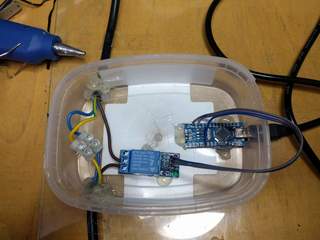
Then, I applied liberal amount of hot-glue to fix power cables and board in place. It worked out pretty well. You will also notice that the relay pin has moved to D2.
Installation
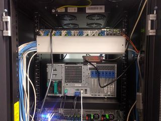
And here it is, installed between existing switch power cable and switch, connected to only USB port still available in rack which is still on network.
cron and serial port
Idea is simple: we'll use cron to ping primary and secondary DNS IP addresses and if any of these fail,
we'll send 0 to turn power off, wait 3 seconds, and send 1 to turn power back on.
Implementation, however, is full of quirks, mostly because we don't want to depend on additional
utilities installed, and we need to wait for Arduino to reset after connecting to serial port
(and to give it time to display value of relay pin) before we start turning power off.
#!/bin/sh -e

ping -q -c 5 193.198.212.8 > /dev/shm/ping && ping -q -c 5 193.198.213.8 >> /dev/shm/ping || (

test -e /dev/shm/reset && exit 0 # reset just once
cp /dev/shm/ping /dev/shm/reset  # store failed ping

date +%Y-%m-%dT%H:%M:%S
cat /dev/shm/ping

dev=/dev/ttyUSB0

trap "exit" INT TERM
trap "kill 0" EXIT

stty -F $dev speed 115200 raw
cat < $dev &
(
        echo
        sleep 3 # wait for reset and startup message
        echo 0  # off
        sleep 3
        echo 1  # on
        sleep 1
) | cat > $dev

kill $!

) # ping subshell
It's started from crontab with user which has dialout group membership so he can open /dev/ttyUSB0:
dpavlin@ceph04:~$ ls -al /dev/ttyUSB0
crw-rw---- 1 root dialout 188, 0 Dec 28 01:44 /dev/ttyUSB0
dpavlin@ceph04:~$ id
uid=1001(dpavlin) gid=1001(dpavlin) groups=1001(dpavlin),20(dialout),27(sudo)
dpavlin@ceph04:~$ crontab -l | tail -1
*/1 *  *   *   *     /home/dpavlin/sw-lib-srv-power-cycle.sh
This will execute script every minute. This allows us to detect error within minute. However, switch boot takes 50s, so we can't just run this script every minute, because it will result in constant switch power cycles. But since we are resetting switch just once this is not a problem.
With this in place, your network switch will not force you to walk to it so you can power cycle it any more.
:-)
And it's interesting combination of sysadmin skills and electronics which might be helpful to someone.
remote access
If we want to access our servers while switch doesn't work, it's always useful to create few shell scripts on remote nodes which will capture IP addresses and commands which you will need to execute to recover your network.
dpavlin@data:~/ffzg$ cat ceph04-switch-relay.sh
#!/bin/sh -xe

ssh 193.198.212.46 microcom -p /dev/ttyUSB0 -s 115200

dpavlin@data:~/ffzg$ cat r1u32-sw-rack3.sh

#!/bin/sh

ssh 193.198.212.43 microcom -p /dev/ttyS1 -s 9600


