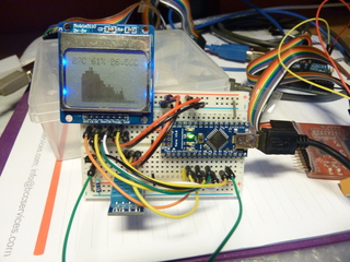
For a last few months, I have been playing around with Arduino and collecting useful parts for my first real project. Last week we purchased Mitsubishi air condition with super-invertor and I wasn't totally happy with the way it operated so I took several afternoons and tried to understand how temperature in my room was varying depending on it's settings. To do that, I built simple temperature monitor using Arduino Nano, two temperature sensors and Nokia 5110 screen. This post tries to document my journey...
Arduino Nano bootloader flashing
When I started buying Arduino parts, I decided I'm cheap bastard and bought Arduino Nano without boot loader flashed, so as first step, I had crash course into ISP programming. As you can see on picture, my board doesn't even have ISP header soldered on it (although it came with one) which might explain why it wasn't pre-flashed. Fortunately, I do have Bus Pirate v3b clone from Sand Box Electronics (essential tool for any micro-controller work in my option) which can also work as ISP programmer for Arduino. On first try, I flashed wrong boot loader (holding ISP header with my finger since it wasn't soldered and using Bus Pirate cables), but I soon learned that Arduino software has helpful boards.txt file from which you can lookup correct boot loader using something like:
dpavlin@blue:~$ grep nano328 /usr/share/arduino/hardware/arduino/boards.txt  | grep bootloader.file
nano328.bootloader.file=ATmegaBOOT_168_atmega328.hex
So, I learned that chap Chinese Arduino clones will give you opportunity to learn something new. I could have used another Arduino for that also, but at the time I didn't have any. Lesson learned, always buy two of each components in hope that one of them will work.
Temperature sensors, display and parts
Having Arduino alone isn't really useful, so I decided to try different on-line shops and collect various parts needed for this project:
- Solderless Breadboard with 400 Tie-Point
- Breadboard Jumper Wires
- Breadboard Jumper Wire Set
- DHT11 1-Wire Single Pin Thermometer/Hygrometer Module
- DS18B20 Programmable Resolution 1-Wire Digital Thermometer
- Arduino Compatible 1.6" Nokia 5110 LCD Module with Blue Backlit
I also have two temperature sensors. I started with DHT11 (mounted on small board with useless red power led - I wouldn't recommend that for next project) which is nice and provides temperature and humidity reading, but I don't get any decimal places in it's output. It's left temperature reading on display. Than I remembered that I have couple of DS18B20 sitting in drawer so I added a 4.7K resistor and hooked it up. This is where things become much more interesting - it's much more accurate that DHT11 so I decided to use that value to draw graph (and display right temperature reading with two decimal places). I also noticed that temperature readings differ by 1 degree or so between sensors.
And a little bit of software
One of main reasons why I'm excited about Arduino is it's software support. While it's a shame that there isn't anything like central repository of software libraries (no, wiki pages at Arduino site doesn't count as one) it's really nice that you can find libraries for everything you might need. This does introduce another problem: now to track all those libraries and your project?
I decided to use git and track everything in my ~/Arduino directory. Initially I was hoping that every library will have upstream git repository so I could use git modules to track them, but some of them don't so I just add them to my repo. This works quite well (if I remember to save sketch before trying to commit it). I started with DHT11 library example and continue adding other parts of code to it. Then I added Arduino Library for Dallas Temperature ICs which in turn uses OneWire to support DS18B20 which doesn't really speak normal i2c protocol. With that working (and reporting temperature back through serial port) it seemed like some kind of local display is in order. So I took Nokia 5110 display I had handy (which I really prefer to other solutions - it's cheap and can display graphic) and took Adafruit driver for PC8544 which in turn again needed Adafruit GFX graphics core library. It seems like mess by now, but it's quite workable and easy to hook together. Only thing that I had to take care is that name of directory within ~/Arduino/libraries should be same as library name itself, which isn't same as name of upstream repository. Oh, well...
This is where (some) form of real development kicked in. I decided to make small circular buffer for DS18B20 readings and draw that as scrolling graph, RRD style. As last step I also added PWM driven back-light to display which is off if value didn't change, half-dimmed if current temperature is lower than previous one or full brightness if it's higher (warning, warning: melting in progress :-) If can take a look at source of DHT11 DS18B20 temperature monitor sketch in all it's 5k glory if you wish. I will probably add average of last three readings for back-light brightness and reduce serial output to format which is better usable for real RRD graphs, but so far this has been useful and fun project. I also understand my air condition operation a little better now :-)
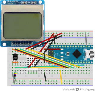
Finally, I used Fritzing to capture schematic output of this project so I don't have to write down pin mappings somewhere. It's somewhat unstable, especially if you try to edit custom parts (I replaced red LCD breakout board with the one which I have) but overall it's a great way to produce structured info about your breadboard view. Having ability to copy/paste elements from other drawing (DHT11 in this case) saved me from defining another custom element.
For some reason, I'm not getting correct schematic view for DS18B20. I might have defined something wrong for it or I just don't know how to correctly use Fritzing yet.