One of simplest home automation projects is to control power sockets. Back in the old days, this involved relays and parallel port, but nowadays you can buy ready made power sockets with remote control which work on 433 MHz IMS band. So next logical step is to replace remote control with computer controlled 433 MHz module. In this post, I will explain how to do it using Arduino or Raspberry Pi.
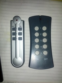
Power sockets with 433 MHz remote control
For this project I decided to try out two different types of power sockets available at our local hardware shop.
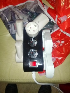
As you can see they are quite different, but any of then will work fine. On the other hand, big bulky square ones have much more useful indicator on then which lights up then they are enabled, while smaller round ones have light which just denotes that they are plugged into electricity but doesn't show status of relay inside of them.
433 MHz modules
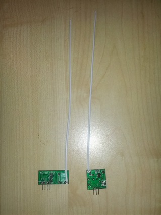
If you want to communicate with these devices you will need some kind of radio modems. For this project, I decided to use cheap 433 MHz radio modules which come in pair: one of them is sender while another is receiver. On picture you can see modules with attached antenna.
I can't stress enough need for antenna. Although modules will work without it, they will have a really poor range of just few centimeters. Antenna should be 172 mm (1/4 of wavelength), and according to my friend who knows something about this things, it's equally bad to have longer or shorter antenna than that. I added 3 mm more for solder joint and it did improve reception and sending range dramatically. You can use any wire for antenna, in my case, I used wire used for wrapping power cords which was long enough to make two antennas.
Arduino
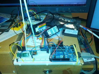
As a first step, I decided to hook them to Arduino Uno to see some waveforms and test rc-switch library. Sure enough it worked on first try. I added project to my ~/Arduino/libraries/RCSwitch directory and used ReceiveDemo_Advanced example to capture signals. Another example, SendDemo enabled me to send signals back to power sockets and turn them on or off. Success on the first try.
With a little bit of tweaking I created RF433_Sockets.ino which allows receiving signals, turning sockets on or off or sending raw binary data to test protocols.
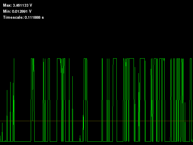
As you can see on picture, I also connected cheap logic analyzer clone to see signals and Bus pirate to monitor signal levels using Bus Pirate oscilloscope python script to make sure that I can connect it to 3.3V level device in next step and I got signals like this on receive pin:
Raspberry Pi
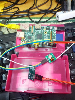
Having verified that signal receiver is generating 3.3V signals (up to 3.6V is OK and mine is 3.46V - electronics isn't exact it seems :-), I decided to hook it up to Raspberry Pi so I will have Internet connected control over my power sockets.
Following link on rc-switch site to port for Raspberry Pi didn't end up all that well. This version of code doesn't support receiving of data, and sending code generates segfaults. However, after a little bit of searching I found blog post about Adding 433 to your Raspberry Pi from NinjaBlocks which inclues link to github repository with code which works fine.
Both versions of code use WiringPi library which is nice way to port Arduino code to Raspberry Pi. When sending signals to 5V devices 3.3V Raspberry Pi GPIO will be usually fine, but when receiving singals, make sure that they are 3.3V or you will fry your Raspberry Pi.
Less than $10 and few hours of work...
Having said all that, it's really easy to create your own home automation system. So I don't see a reason not to do so...Parts list: (assuming you already have Arduino or Raspberry Pi)
- 2 sets 433Mhz RF transmitter and receiver kit for Arduino US $2.77
- 40PCS Dupont Wire Color Jumper Cabl 2.54mm 1P-1P Male to Female 20cm US $2.57 (for Arduino)
- 40PCS Dupont wire 20cm cable Line color 1p-1p pin connector US $2.68 (for Raspberry Pi)