We all read hackaday, and when I read Five Dollar RF Controlled Light Sockets post I decided that I have to buy some. However, if you read comments on original Cheap Arduino Controlled Light Sockets - Reverse Engineering RF post and especially comments, you will soon figure out that ordering same looking product from China might bring you something similar but with different internals.
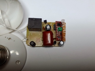
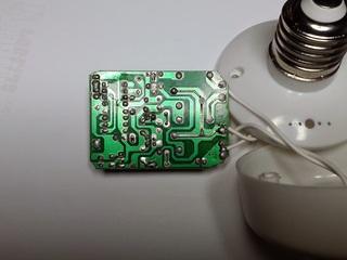
In my case, all four light sockets turn on or off with any button press on remote which was a shame. When I opened remote and socket, I also had bad surprise. My version didn't have any SPI eeprom, but just two chips, ST F081 FB 445 in remote and ST ED08 AFB422 in light bulb (in picture hidden below receiver board).
But, I already had acquired two sets so I wanted to see what I can do with them. Since I couldn't read eeprom to figure out code, I decided to use rtl-sdr to sniff radio signals and try to command them using cheap 315 MHz Arduino module.
I used gqrx to sniff radio signals and I was not pleased. Remote drifted all over the place mostly around 316 MHz and it was some trial and error to capture signals which are generated when buttons are pressed. However, I have verified that it's sending same signal multiple times no matter which keys I press (which would explain why four pins on remote are soldered together).
After a while I had two traces (since I have two sets of light sockets) and could decode binary data which is sent from following picture:
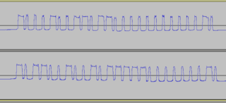
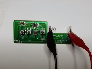
How I knew that one set is transmitting 1000100110110000000000010 and another one 1011001001011111000000010. From looking into timing in audacity, it seemed that each bit is encoded in short-long or long-short sequence where short one is about third of long one, and one bit is about 1200 ms. I cheated here a little and stuck scope into scope into transmit trace on remote to verify length of pulses just to be sure.
So as next step I wrote simple Arduino sketch to try it out:
#define TX_PIN 7
#define LED_PIN 13

char *code = "1000100110110000000000010";
//char *code = "1011001001011111000000010";

void setup() {
  pinMode(LED_PIN, OUTPUT);
  pinMode(TX_PIN, OUTPUT);
}

void loop() {
  digitalWrite(LED_PIN, HIGH);

  for(int i = 0; i < strlen(code); i++) {
    int i1 = 300;
    int i2 = 900;
    if (code[i] == '1' ) {
      i1 = 900;
      i2 = 300;
    }
    digitalWrite(TX_PIN, HIGH);
    delayMicroseconds(i1);
    digitalWrite(TX_PIN, LOW);
    delayMicroseconds(i2);
  }

  digitalWrite(LED_PIN, LOW);
  delay(3000);
}
So, I compiled it, uploaded to Arduino and... nothing happens.
Back to the drawing board, I guess.
When I was looking into gqrx I could see that signal is sent as long as I'm holding button up to 10 seconds. From experience before I know that this cheap receivers need some tome to tune into frequency so next logical step was to send same signal multiple times. And guess what, when I sent same singal twice with 2000 ms delay between them everything started to work.
Again somewhat. Light socket in far corner of hall seemed to have problems receiving signal which would put two light socket in hall in opposite state: one would be on and another would be off. This was fun, and could be fixed with simple antenna on Arduino module (since currently I don't have any) but I will conclude that your IoT device should send different codes for on and off state so something like this won't happen to you.
Then I got carried away and added commands to change all parameters to experiment how sensitive receiver is. You can find full code at http://git.rot13.org/?p=Arduino;a=blob;f=light_sockets/light_sockets.ino With this experiments I found out that you don't have to be precise with timings (so my oscilloscope step was really not needed). Receiver works with 500 ms low and 1100 ms high (for total of 1600 ms per bit) on high end, down to 200 ms for low and 800 ms for high (for total of 1000 ms per bit).
I suspect that chips are some kind of 26 bit remote encoders/decoders but I can't find any trace of datasheet on Internet. This is a shame, because I suspect that it's possible to program light sockets to respond to any code and in theory address each of them individually (which was my goal in beginning). However poor construction quality, and same code for on and off state (combined with poor reception) makes me wonder if this project is worth additional time.