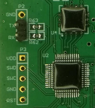
If you ever needed to connect to JTAG or SWD on stm32 and tried to search for solutions on Internet, you quickly realized that amount of information is overwhelming. However, fear not. If you have Raspberry Pi and few wires, you are already half-way there.

For me, this whole adventure started when I got non-working sensor which had swd header and blob over chip. This was not my first swd experiment. Thanks to great Hackaday Remoticon 2020 The Hackers Guide to Hardware Debugging by Matthew Alt I had already tried to connect using swd from Raspberry Pi to bluepill (which is stm32f103) so I had some experience with that. Now I also had unknown device so I can try what I can do with it.
For a start, you can notice that device have UART TX and RX pins already soldered, so first step was to connect normal 3.3V serial to those pins and see if we have some output. And I did. I could see that it's contacting sensor chip and trying to initiate NBIoT connection, but fails. So next step was to solder SWD pins, and connect them to Raspberry Pi. For that, I created openocd configuration rpi4-zc-swd.cfg and uncommeted bottom of configuration to get first idea what chip is on the board (since it's covered with blob):
swd newdap chip cpu -enable
dap create chip.dap -chain-position chip.cpu
target create chip.cpu cortex_m -dap chip.dap
init
dap info
I did made some assumptions where, for example that chip is cortex_m, but since it has swd header, there was a good chance it was.
However, since this sensor tries to get measurements in some configurable interval, just connecting using openocd didn't work since sensor after power up and sensor check went into sleep. While I could re-plug sensor repeatably, this is not needed since there is also rst pin (connected to pin 22 on Raspberry pi) which we can toggle from shell using:
raspi-gpio set 22 op
raspi-gpio get 22
raspi-gpio set 22 dl
raspi-gpio get 22
raspi-gpio set 22 dh
raspi-gpio get 22
This woke up sensor again, and I was able to connect to it using openocd and was greeted with following output:
root@rpi4:/home/pi/openocd-rpi2-stm32# openocd -f rpi4-zc-swd.cfg
Open On-Chip Debugger 0.11.0+dev-00062-g6405d35f3-dirty (2021-03-27-16:05)
Licensed under GNU GPL v2
For bug reports, read
        http://openocd.org/doc/doxygen/bugs.html
Info : BCM2835 GPIO JTAG/SWD bitbang driver
Info : clock speed 100 kHz
Info : SWD DPIDR 0x0bc11477
Info : chip.cpu: hardware has 4 breakpoints, 2 watchpoints
Info : starting gdb server for chip.cpu on 3333
Info : Listening on port 3333 for gdb connections
AP ID register 0x04770031
        Type is MEM-AP AHB3
MEM-AP BASE 0xf0000003
        Valid ROM table present
                Component base address 0xf0000000
                Peripheral ID 0x00000a0447
                Designer is 0x0a0, STMicroelectronics
                Part is 0x447, Unrecognized
                Component class is 0x1, ROM table
                MEMTYPE system memory present on bus
So, indeed this was STMicroelectronics chip, but unknown model. However, using Info : SWD DPIDR 0x0bc11477 and googling that I figured out that it's probably STM32L0xx which again made sense.
So I started openocd -f rpi4-zc-swd.cfg -f target/stm32l0_dual_bank.cfg and telnet 4444 to connect to it and I was able to dump flash. However, I had to be quick since sensor will power off itself after 30 seconds or so. Solution was easy, I toggled again rst pin and connected using gdb which stopped cpu and left sensor powered on.
However, all was not good since quick view into 64K dump showed that at end of it there was partial AT command, so dump was not whole. So I opened STM32L0x1 page and since mcu was LQFP 48 with 128k my mcu was STM32L081CB. So I restarted openocd -f rpi4-zc-swd.cfg -f target/stm32l0_dual_bank.cfg and got two flash banks:
> flash banks
#0 : stm32l0.flash (stm32lx) at 0x08000000, size 0x00010000, buswidth 0, chipwidth 0
#1 : stm32l0.flash1 (stm32lx) at 0x08010000, size 0x00010000, buswidth 0, chipwidth 0
So I was able to dump them both and got full firmware. It was also very useful, because at one point I did write flash in gdb instead in telnet 4444 connection and erased one of sensors which I was able to recover using dump which I obtained.
This however, produced another question for me: since flash is same on all sensors, where are setting which can be configured in sensor (and wasn't changed by re-flashing firmware). Since chip also has 6k of eeprom this was logical place to put it. However, openocd doesn't have bult-in support to dump eeprom from those chips. However, I did found post Flashing STM32L15X EEPROM with STLink under Linux which modified openocd to support reading and writing of eeprom back in 2015 but is not part of upstream openocd.
I didn't want to return to openocd from 2015 or port changes to current version, but I didn't have to. Since I was only interested in dumping eeprom I was able to dump it using normal mdw command:
> mdw 0x08080000 15361536 is number of 32-bit words in 6k eeprom (1536 * 4 = 6144). And indeed setting which are configurable where stored in eeprom.
This was fun journey into openocd and stm32, so I hope this will help someone to get started. All configuration files are available at https://github.com/dpavlin/openocd-rpi2-stm32.