It all started more than a week ago when I was given 10x10 panel of ws2812 leds designed to be broken apart into individual boards. I might have said at that moment: "It is a panel, it's just missing a few wires", and so this story begins...

IMG_20200301_130434.jpg

It took me the whole day to add those few wires and turn it into panel.

IMG_20200301_163206.jpg

I started testing it using Arduino Nano with wrong FastLED example (which supports just 4 ws8212) and wondered why I'm not getting the whole panel to light up. After some sleep, I tried Adafruit example, fixed one broken data out-in wire in middle of panel and I got this:

Thumbnail image for IMG_20200302_105830.jpg

So, playing video on this panel should be easy now, right?

First, I had to make a choice of platform to drive the panel. While my 10x10 panel with 100 leds needed just 300 bytes for single frame, I didn't want to have a video sending device wired to it. So, esp8266 was logical choice to provide network connectivity to the panel without usb connection (which we still need, but just for power).

At first, I took the Lolin Node MCU clone, which doesn't have 5V broken out (why?), and its VIN pin has a diode between USB 5V pin and VIN, and diode voltage drop is enough to make ws2812 dark all the time.
Switching to Weemos D1 mini did help there, but what to run on it? I found some examples that where too clever for me (for 8x8 panel, they use jpeg and just decode single 8x8 block to show it which won't work for my 10x10 panel).
After a bit of googling, it seems to me that https://github.com/Aircoookie/WLED project is somewhat of Tasmota for WS2812 on ESP8266, so I decided to use it. While it's not designed to support WS2812 matrix but simple stripes, it has UDP realtime control which enables it to send 302 byte UDP packet (300 bytes of RGB data and two byte header).

So I started writing scripts which are at https://github.com/dpavlin/WLED-video to first convert video to raw frames using something as simple as ff2rgb.sh:

dpavlin@nuc:/nuc/esp8266/WLED-video$ cat ff2rgb.sh
#!/bin/sh -xe

f=$1

test ! -d $f.rgb && mkdir $f.rgb || rm -v $f.rgb/*.png
ffmpeg -i $f -vf scale=10x10 $f.rgb/%03d.png
ls $f.rgb/*.png | xargs -i convert {} -rotate 180 -gamma 0.3 -depth 8 {}.rgb
To send frames I wrote simple send.pl script. I would have loved to be able to use bash udp support or some standard utility (like netcat or socat) to send frames, but null values in data didn't work well with shell pipes and I wasn't able to make it work.
I also figured out that I have to modify gamma values for my frames so that colors are somewhat more correct (I had flame video which had blue hues on it without gamma correction). This is somewhat strange because WLED does have gamma correction for colors turned on, but it doesn't help and turning it off also doesn't help. So, gamma correction in pre-processing it is...

And since I already had perl script to send UDP packets, I decided to open ffmpeg from it and make single script ff2wled.pl which sends video to panel like this:

dpavlin@nuc:/nuc/esp8266/WLED-video$ ./ff2wled.pl rick.gif

rick-panel.gif

Was it all worth it? Honestly, no. The panel is small enough that video playback is really too much for such small resolution and it would be so much easier to buy ready-made panel with more leds. But, I did learn a few tricks with ffmpeg, and hopefully somebody else will benefit from this post.

I don't have TV remote. I did get one, but as soon as I installed TV I realized that it's quite annoying to find remote to turn TV on when I sit with my wireless keyboard (computer is the only device connected to TV). So, I added keyboard shortcut using xbindkeys, addad IR led to Raspberry Pi, configured lirc and was happy about it. And then, buster with kernel 4.19 came and everything changed.

Send IR to TV

Upgrade to 4.19 kernel should be easy, only thing you have to do (if your IR sending diode is on pin 18) is to enable new overlay:

# pwm works only on 18
dtoverlay=pwm-ir-tx,gpio_pin=18
This does not work reliably for me on Raspberry Pi 1. My TV detect roughly every third key press and this makes command-line TV remote solution useless because you can use TV menus to setup picture any more.

So, I had to do something. Getting up and pressing button on TV is not something that I can live with after having this automation working for year (and TV remote was missing by now). But, I had all required components.

Few weeks ago, I removed IR send/receive board from RMmini 3 and documented it's pinout:

RMmini3-ir-pinout.jpg

I was also in the middle of flashing Sonoff-Tasmota to bunch of Tackin plugs so it seemed like logical step to flash Tasmota to NodeMCU board, connect RMmini 3 IR board to it and give it a try. And I'm glad I did.

I used to have http server (simple perl script) running on Raspberry Pi which used irsend to send IR codes. From xbindkey perspective, my configuration used curl and all I had to do to get IR working again was changing my script to use mosquitto instead of irsend:

mosquitto_pub -h rpi2 -q 2 -t cmnd/ir/IRSend -m '{"protocol": "NEC","bits": 32, "data": 0x20DF10EF}'
At this point I realized that I can put this into .xbindkeyrc and contact esp8266 directly. This didn't work... You can't have double quotes in commands which are executed and I had to put it into shell script and call that.

And to my amazement, there was noticeable difference in response time of TV. In retrospect, this seemed obvious because my TV nuc is much faster than Raspberry Pi, but this was probably the most unexpected benefit of this upgrade.

When I said that you have to connect IR receiver and sender on NodeMCU pins, you have to take care not to hit pins that have special purpose on power-up. For example, if you connect something that will pull to ground on powerup (IR led for example) to gpio0 esp8266 will stay in boot loader mode. gpio2 and gpio16 are led pins on nodemcu board, so don't use them (and define them as Led1i and Led2i in configuration).

Having LEDs configured in tasmota allows me to extend my shell script and blink led after IR code has been sent:

dpavlin@nuc:~$ cat tv-on.sh 
#!/bin/sh
mosquitto_pub -h rpi2 -q 2 -t cmnd/ir/IRSend -m '{"protocol": "NEC","bits": 32, "data": 0x20DF10EF}'
mosquitto_pub -h rpi2 -q 2 -t cmnd/ir/LedPower -m 1
mosquitto_pub -h rpi2 -q 2 -t cmnd/ir/LedPower -m 0

Send IR to HVAC

By pure luck, just a few days latter, my friend wanted to control his ACs from computer. Again tasmota came to the rescue. Since HVAC support in tasmota will increase firmware size over 512Kb (which breaks OTA upgrade on 1Mb modules) it's not compiled in by default. However, you can edit sonoff/my_user_config.h and uncomment it:

    #define USE_IR_HVAC                          // Support for HVAC systems using IR (+3k5 code)
    #define USE_IR_HVAC_TOSHIBA                  // Support IRhvac Toshiba protocol
    #define USE_IR_HVAC_MITSUBISHI               // Support IRhvac Mitsubischi protocol
    #define USE_IR_HVAC_LG                       // Support IRhvac LG protocol
    #define USE_IR_HVAC_FUJITSU                  // Support IRhvac Fujitsu protocol
    #define USE_IR_HVAC_MIDEA                    // Support IRhvac Midea/Komeco protocol
However, if you want to keep OTA update working, you will also have to turn off some other configuration options (I don't use Domoticz or Home Assistant) to keep firmware size below 512Kb.

To create IR sender, I decided to add IR LED, transistor and resistor to existing ESP-01 module with DHT11 board (which has 3.3v regulator on it) according to the following DaveCAD(tm) drawing:

ir-send-schematics.jpg

If you are wondering why I'm connecting IR led to RX pin (gpio3), it's because gpio0 is special, gpio2 is already used for dht11 and TX (which is gpio1) is also special. Since we don't need serial, using single pin left RX saves the day. And this is the picture of the first prototype (on which I tried all pins until I settled on RX):

esp-01-dht11-ir.jpg

With all this in place and quick re-flash, we where than able to issue commands like this to control AC:

mosquitto_pub -h rpi2 -t 'cmnd/ir/irhvac' -m '{ "Vendor": "Mitsubishi", "Power": 1, "Mode":"Cold", "Temp": 25}'

mosquitto_pub -h rpi2 -t 'cmnd/ir/irhvac' -m '{ "Vendor": "Mitsubishi", "Power": 0}'
So, with all this, I hope that you don't have any excuse not to control your IR devices from a command-line.

Update: Just to make sure that you don't think this is my best soldering ever here is also picture of 4 more modules which will be distributed to my friends.

IMG_20190802_134752 (1).jpg

Our top-of-switch rack decides to die randomly from time to time. It was somewhat inconvenient since it also killed most of our infrastructure including primary and secondary DNS so I needed a solution quickly. Since different rack is still on the network, I should be able to hack something and finally connect my Arduino knowledge and sysadmin realm, right? Think of it as power cycle watchdog based on network state.

First thing was to figure out what was happening with the switch. It seemed like it was still working (LEDs did blink), but only thing that helped was power cycle. So as a first strep, I connected serial console (using RS-232 extension cable) to on-board serial port (since it doesn't seem to work using cheap CH340 based USB serial dongles) and I didn't expect this:

0x37491a0 (bcmCNTR.0): memPartAlloc: block too big 6184 bytes (0x10 aligned) in partition 0x30f6d88
0x3cd6bd0 (bcmCNTR.1): memPartAlloc: block too big 6184 bytes (0x10 aligned) in partition 0x30f6d88
0x6024c00 (simPts_task): memPartAlloc: block too big 1576 bytes (0x10 aligned) in partition 0x30f6d88
When I google messages like this I get two types of answers:
  1. beginner questions about VxWorks which summ up to: you have memory leak
  2. errors from switches with boardcomm chipset from various vendors
There is basically no solution. We are running latest firmware, and internet doesn't have any idea what to do.
Serial console did emit a lot of messages, but didn't respond to input at all. I would at last expect that watchdog timer in the switch will reset it once it manages to fragment it's own memory so much that it has stopped forwarding packets, oh well.... What else can I do?

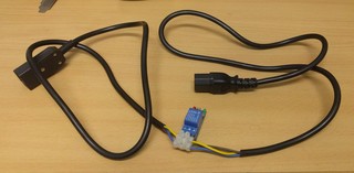
IEC power cable with relay

I wanted something what I can plug in between the existing switch with IEC power connector with USB on the other end that can be plugged into any USB port for control.

IMG_20181219_172912.jpg

Since this is 220V project (and my first important one), I tried to do it as safe as possible.

  • I started with a power cable, that I cut in half and put ferrules on all wires to be sure that connectors will grip those wires well.
  • Then I replaced the power plug with IEC connector so it's can be inserted in any power cable. In this case, we soldered wires ends, since ferrules where too big to fit into connector housing. We did wrap a wire around a screw in a connector correctly, so tightening the screw will not displace the wire.
  • Finally I connected cheap 10A 250VAC relay which should be enough for fully loaded 48 port gigabit network switch that draws round 80W.
  • To make sure that rest of the system can't just power cycle device connected at any time, I connected live wire through normally closed pins on a relay. This means that this cable should work as-is (without powering it at all) and when powered, since board has pull-up resistor on the relay to VCC, the relay will be in the same sate, passing power to device.
  • Finally I checked all three power cable wires with multi-meter and got around 0.2 ohms which mans that whole thing works for now.
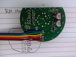
At this point we should note that this relay board has only three pins (IN, GND and VCC) and has no optical isolation to 220V side. Since isolation would require us to provide additional power supply for 220V side, it was acceptable a risk.

Putting it into a box

I really wanted to somehow fix wires and protect the bottom of the relay board (which has 220V on it) from shorting to something, so I used an old box from a dairy product and created a housing for electronics.

IMG_20181220_095707.jpg

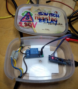
If you look carefully, you will notice that I had to cut the case all the way through to pass through the power cable (that has a zip-tie on inside to prevent it from pulling out). The Case will be fixed using hot glue and a lid, so this won't be a problem.
Warning and label on the lid is also nice touch, and shouldn't be skipped when creating a thing which you won't be only user of.

Arduino software

You will also notice that relay is connected to A7, which didn't work out. Let me explain:
The idea is to use Arduino default pin state (INPUT) as a state in which the pin will stay most of the time. This makes pin floating, and we can inspect pull-up on relay board and report if we see it. When we want to activate the relay, we'll flip pin to output, pull it down, and activate the relay.
Code is available at https://github.com/dpavlin/Arduino-projects/blob/nuc/power_cycle/power_cycle.ino and it can't be much simpler:

/*
 * power cycle switch
 * 
 * relay is connected across 5V relay through normally closed pins so that failure of arduino doesn't kill power to switch.
 * to activate relay on this board, signal pin has to be pulled to ground.and coil draw is 76 mA when active
 * board has pull up on input pin to it's vcc
*/

#define RELAY_PIN 2

void setup() {
  Serial.begin(115200);

  pinMode(LED_BUILTIN, OUTPUT);

  pinMode(RELAY_PIN, INPUT); // don't modify pin state
  Serial.print("Relay pin on reset: ");
  Serial.println(digitalRead(RELAY_PIN));
}

void loop() {
  if ( Serial.available() ) {
    char c = Serial.read();
    if ( c == '0' ) {
      Serial.print("L");
      pinMode(RELAY_PIN, OUTPUT);
      digitalWrite(RELAY_PIN, LOW); // activate relay

      digitalWrite(LED_BUILTIN, HIGH); // led on
    } else if ( c == '1' ) {
      Serial.print("H");
      pinMode(RELAY_PIN, INPUT);

      digitalWrite(LED_BUILTIN, LOW); // led off
    } else {
      Serial.print(c);
    }
  }
}
Simple is good: I toyed with idea of automatically releasing the relay from Arduino code, and when I started to implement timeout configuration on Arduino side, I remembered what this will be plugged into random server USB port, without avrdude and any handy way to update firmware on it, so I decided to just leave simplest possible commands:
  • 1 - ON (outputs H) - power on, default
  • 0 - OFF (outputs L) - power off, relay active
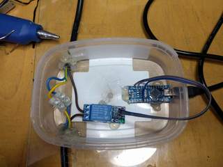
Hot glue galore

Then, I applied liberal amount of hot-glue to fix power cables and board in place. It worked out pretty well. You will also notice that the relay pin has moved to D2.

IMG_20181220_111345.jpg

Installation

IMG_20181220_132632.jpg

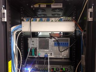
And here it is, installed between existing switch power cable and switch, connected to only USB port still available in rack which is still on network.

cron and serial port

Idea is simple: we'll use cron to ping primary and secondary DNS IP addresses and if any of these fail, we'll send 0 to turn power off, wait 3 seconds, and send 1 to turn power back on.
Implementation, however, is full of quirks, mostly because we don't want to depend on additional utilities installed, and we need to wait for Arduino to reset after connecting to serial port (and to give it time to display value of relay pin) before we start turning power off.

#!/bin/sh -e

ping -q -c 5 193.198.212.8 > /dev/shm/ping && ping -q -c 5 193.198.213.8 >> /dev/shm/ping || (

test -e /dev/shm/reset && exit 0 # reset just once
cp /dev/shm/ping /dev/shm/reset  # store failed ping

date +%Y-%m-%dT%H:%M:%S
cat /dev/shm/ping

dev=/dev/ttyUSB0

trap "exit" INT TERM
trap "kill 0" EXIT

stty -F $dev speed 115200 raw
cat < $dev &
(
        echo
        sleep 3 # wait for reset and startup message
        echo 0  # off
        sleep 3
        echo 1  # on
        sleep 1
) | cat > $dev

kill $!

) # ping subshell
It's started from crontab with user which has dialout group membership so he can open /dev/ttyUSB0:
dpavlin@ceph04:~$ ls -al /dev/ttyUSB0 
crw-rw---- 1 root dialout 188, 0 Dec 28 01:44 /dev/ttyUSB0
dpavlin@ceph04:~$ id
uid=1001(dpavlin) gid=1001(dpavlin) groups=1001(dpavlin),20(dialout),27(sudo)
dpavlin@ceph04:~$ crontab -l | tail -1
*/1 *  *   *   *     /home/dpavlin/sw-lib-srv-power-cycle.sh
This will execute script every minute. This allows us to detect error within minute. However, switch boot takes 50s, so we can't just run this script every minute, because it will result in constant switch power cycles. But since we are resetting switch just once this is not a problem.

With this in place, your network switch will not force you to walk to it so you can power cycle it any more. :-)
And it's interesting combination of sysadmin skills and electronics which might be helpful to someone.

remote access

If we want to access our servers while switch doesn't work, it's always useful to create few shell scripts on remote nodes which will capture IP addresses and commands which you will need to execute to recover your network.

dpavlin@data:~/ffzg$ cat ceph04-switch-relay.sh 
#!/bin/sh -xe

ssh 193.198.212.46 microcom -p /dev/ttyUSB0 -s 115200

dpavlin@data:~/ffzg$ cat r1u32-sw-rack3.sh 

#!/bin/sh

ssh 193.198.212.43 microcom -p /dev/ttyS1 -s 9600
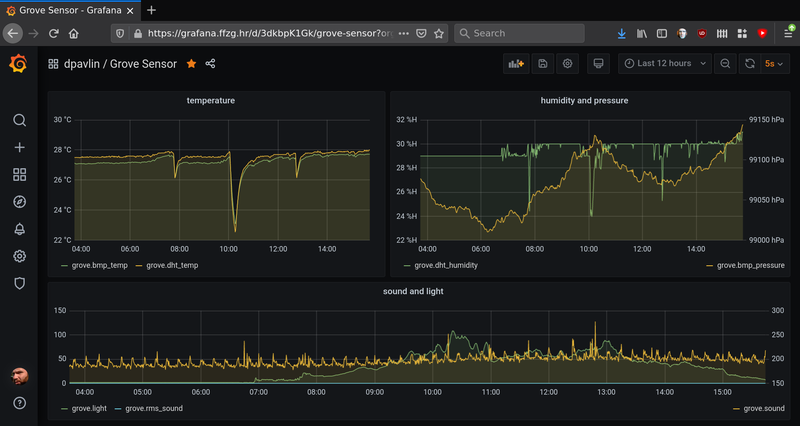
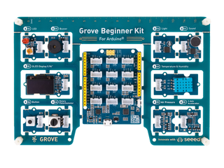
This week I learned valuable lesson: if you are using MIPS from 2008 in your RAID controller, you can't really expect it to be faster than more modern Intel CPU when doing RAID 10 on disks.

It all started with failure of SSD in our bcache setup which sits on top of MegaRAID RAID10 array. Since this required me take one of ganeti nodes down, it was also a good opportunity to add one more disk (we where running 6 disks and one SSD) and switch to software md RAID10 so we can use all 7 disks in RAID10. In this process, I did some benchmarking and was shocked with results.

First, let's see original MegaRAID configuration:

# lsblk --scsi -m
NAME HCTL       TYPE VENDOR   MODEL             REV TRAN NAME   SIZE OWNER GROUP MODE
sda  0:0:6:0    disk ATA      WDC WD1002FBYS-1 0C12      sda  931.5G root  disk  brw-rw----
sdb  0:0:7:0    disk ATA      INTEL SSDSC2BW24 DC32      sdb  223.6G root  disk  brw-rw----
sdc  0:2:0:0    disk DELL     PERC H310        2.12      sdc    2.7T root  disk  brw-rw----
# hdparm -tT /dev/sdc

/dev/sdc:
 Timing cached reads:   13920 MB in  1.99 seconds = 6981.76 MB/sec
 Timing buffered disk reads: 1356 MB in  3.00 seconds = 451.81 MB/sec
and let's compare that with JBOD disks on controller and creating md array:
# hdparm -Tt /dev/md0
/dev/md0:
 Timing cached reads:   13826 MB in  1.99 seconds = 6935.19 MB/sec
 Timing buffered disk reads: 1888 MB in  3.01 seconds = 628.05 MB/sec
So, TL;DR is that you are throwing away disk performance if you are using hardware RAID. You didn't expect that? I didn't. In retrospect it's logical that newish Intel CPU can process data much faster than slowish MIPS on RAID controller, but on the other hand only difference is RAID overhead because same controller is still handling disks with software raid.

I also wrote document with a lot of console output and commands to type if you want to do the same: https://github.com/ffzg/gnt-info/blob/master/doc/megaraid-to-md.txt

Today I was explaining xclip utility and found this useful snippet which I wrote back in 2011 that allows you to edit browser textarea in terminal using vi with syntax highlighting.

#!/bin/sh

# workflow:
# 1. focus textarea in browser you want to edit
# 2. press ctrl+a then ctrl+c
# 3. switch to terminal and start this script with optional extensioni for highlight: xclip-vi html
# 4. edit file in vi, and save it
# 5. switch back to browser, and press ctrl+v in already selected textarea

ext=$1
test -z "$ext" && ext=txt

xclip -out > /tmp/$$.$ext && vi /tmp/$$.$ext && xclip -in -selection clipboard < /tmp/$$.$ext

xclip-vi.sh github gist

These days, my work seems more like archeology than implementing newest and coolest web technologies, but someone has to keep an eye on old web servers which are useful to people.

In this case, it's two major Debian releases upgrade which of course did result in some amount of breakage as you would expect. Most of breakage was easy to fix, but we had one site which had only pyc files, and python2.6 with correct modules wasn't supported on current distribution.

First idea was to use python de-compiler to generate source python files, and this only got me to different python errors which I didn't know how to fix. so, this was dead end.

I did have a backup of machine before upgrade on zfs pool, so next logical idea was to run minimal amount of old binaries to keep the site up. And I decided to do it in chroot so I can easily share mysql socket from current installation into pre-upgrade squeeze. Let's see what was involved in making this happen.

1. make writable copy of filesystem

Our backups are on zfs pool, so we cloned all three disks into same layout as they are mounted on filesystem:

2018-06-08.10:07:53 zfs clone lib15/backup/pauk.ffzg.hr/0@2018-05-01 lib15/export/pauk.ffzg.hr
2018-06-08.10:08:19 zfs clone lib15/backup/pauk.ffzg.hr/1@2018-05-01 lib15/export/pauk.ffzg.hr/home
2018-06-08.10:08:38 zfs clone lib15/backup/pauk.ffzg.hr/2@2018-05-01 lib15/export/pauk.ffzg.hr/srv

2. nfs export it to upgraded server

Take a note of crossmnt parameter, this will allow us to mount all descending filesystems automatically.

root@lib15:~# grep pauk /etc/exports 
/lib15/export/pauk.ffzg.hr 10.21.0.2(rw,fsid=2,no_subtree_check,no_root_squash,crossmnt)
root@lib15:~# exportfs -va
exporting 10.21.0.2:/lib15/export/pauk.ffzg.hr

3. mount nfs export

root@pauk:~# grep squeeze /etc/fstab
10.21.0.215:/lib15/export/pauk.ffzg.hr  /mnt/squeeze    nfs     defaults,rw     0 0

4. start chroot with old version of service

To make this work, I first edited apache configuration in chroot to start it on different port, and configured front-end server to redirect site to new port.

root@pauk:/home/dpavlin# cat chroot-squeeze.sh 

to=/mnt/squeeze

mount --bind /dev $to/dev
mount --bind /sys $to/sys
mount --bind /proc $to/proc

mount --bind /var/run/mysqld/ /mnt/squeeze/var/run/mysqld/

/usr/sbin/chroot $to /etc/init.d/apache2 start

5. redirect apache traffic to server in chroot

You will have to insert something like this in current apache configuration for vhost:

<Proxy http://127.0.0.1:18080/*>
    Order allow,deny
    Allow from all
</Proxy>
<Location /german2/>
    RequestHeader set Host "www.ffzg.unizg.hr"
    ProxyPreserveHost On
    ProxyPass        http://127.0.0.1:18080/german/
    ProxyPassReverse http://127.0.0.1:18080/german/
</Location>

You might scream at me that in days of containers, systemd and other better solutions chroot is obsolete. In my opinion, it's just a right tool for a job from time to time, if you have backup :-)

This year on DORS/CLUC 2018 I decided to talk about device tree in Linux kernel, so here are blurb, presentation and video of that lecture.

You have one of those fruity *Pi arm boards and cheep sensor from China? Some buttons and LEDs? Do I really need to learn whole new scripting language and few web technologies to read my temperature, blink a led or toggle a relay?
No, because your Linux kernel already has drivers for them and all you need is device tree and cat.