Results matching “linux”

Configuring shibboleth is always somewhat confusing for me, so I decided to write this blog post to document how configuration for dspace is done and debugged.

This information is scattered over documentation and dspace-tech mailing list so hopefully this will be useful to someone, at least me if I ever needed to do this again.

First step is to install mod-shib for apache: apt install libapache2-mod-shib Now there are two files which have to be modified with your information, /etc//shibboleth/shibboleth2.xml which defines configuration and /etc/shibboleth/attribute-map.xml to define which information will be passwd from shibboleth to application.

attribute-map.xml

Here we have to define headers which dspace expects, so it can get information from upstream idenitity provider.

diff --git a/shibboleth/attribute-map.xml b/shibboleth/attribute-map.xml
index 1a4a3b0..a8680da 100644
--- a/shibboleth/attribute-map.xml
+++ b/shibboleth/attribute-map.xml
@@ -163,4 +163,34 @@
</Attribute>
-->

+ <!-- In addition to the attribute mapping, DSpace expects the following Shibboleth Headers to be set:
+ - SHIB-NETID
+ - SHIB-MAIL
+ - SHIB-GIVENNAME
+ - SHIB-SURNAME
+ These are set by mapping the respective IdP attribute (left hand side) to the header attribute (right hand side).
+ -->
+ <Attribute name="urn:oid:0.9.2342.19200300.100.1.1" id="SHIB-NETID"/>
+ <Attribute name="urn:mace:dir:attribute-def:uid" id="SHIB-NETID"/>
+ <Attribute name="hrEduPersonPersistentID" nameFormat="urn:oasis:names:tc:SAML:2.0:attrname-format:basic" id="SHIB-NETID"/>
+
+ <Attribute name="urn:oid:0.9.2342.19200300.100.1.3" id="SHIB-MAIL"/>
+ <Attribute name="urn:mace:dir:attribute-def:mail" id="SHIB-MAIL"/>
+ <Attribute name="mail" nameFormat="urn:oasis:names:tc:SAML:2.0:attrname-format:basic" id="SHIB-MAIL"/>
+
+ <Attribute name="urn:oid:2.5.4.42" id="SHIB-GIVENNAME"/>
+ <Attribute name="urn:mace:dir:attribute-def:givenName" id="SHIB-GIVENNAME"/>
+ <Attribute name="givenName" nameFormat="urn:oasis:names:tc:SAML:2.0:attrname-format:basic" id="SHIB-GIVENNAME"/>
+
+ <Attribute name="urn:oid:2.5.4.4" id="SHIB-SURNAME"/>
+ <Attribute name="urn:mace:dir:attribute-def:sn" id="SHIB-SURNAME"/>
+ <Attribute name="sn" nameFormat="urn:oasis:names:tc:SAML:2.0:attrname-format:basic" id="SHIB-SURNAME"/>
+
</Attributes>

shibboleth2.xml

This is main configuration file for shibd. First we need to add OutOfProcess and InProcess to include useful information in shibd.log which are very useful.

diff --git a/shibboleth/shibboleth2.xml b/shibboleth/shibboleth2.xml
index ddfb98a..7b55987 100644
--- a/shibboleth/shibboleth2.xml
+++ b/shibboleth/shibboleth2.xml
@@ -2,15 +2,46 @@
xmlns:conf="urn:mace:shibboleth:3.0:native:sp:config"
clockSkew="180">

- <OutOfProcess tranLogFormat="%u|%s|%IDP|%i|%ac|%t|%attr|%n|%b|%E|%S|%SS|%L|%UA|%a" />
+ <!-- The OutOfProcess section contains properties affecting the shibd daemon. -->
+ <OutOfProcess logger="shibd.logger" tranLogFormat="%u|%s|%IDP|%i|%ac|%t|%attr|%n|%b|%E|%S|%SS|%L|%UA|%a">
+ <!--
+ <Extensions>
+ <Library path="odbc-store.so" fatal="true"/>
+ </Extensions>
+ -->
+ </OutOfProcess>

+
+ <!--
+ The InProcess section contains settings affecting web server modules.
+ Required for IIS, but can be removed when using other web servers.
+ -->
+ <InProcess logger="native.logger">
+ <ISAPI normalizeRequest="true" safeHeaderNames="true">
+ <!--
+ Maps IIS Instance ID values to the host scheme/name/port. The name is
+ required so that the proper <Host> in the request map above is found without
+ having to cover every possible DNS/IP combination the user might enter.
+ -->
+ <Site id="1" name="sp.example.org"/>
+ <!--
+ When the port and scheme are omitted, the HTTP request's port and scheme are used.
+ If these are wrong because of virtualization, they can be explicitly set here to
+ ensure proper redirect generation.
+ -->
+ <!--
+ <Site id="42" name="virtual.example.org" scheme="https" port="443"/>
+ -->
+ </ISAPI>
+ </InProcess>
+
<!--
By default, in-memory StorageService, ReplayCache, ArtifactMap, and SessionCache
are used. See example-shibboleth2.xml for samples of explicitly configuring them.
-->

<!-- The ApplicationDefaults element is where most of Shibboleth's SAML bits are defined. -->
- <ApplicationDefaults entityID="https://sp.example.org/shibboleth"
+ <ApplicationDefaults entityID="https://repository.clarin.hr/Shibboleth.sso/Metadata"
REMOTE_USER="eppn subject-id pairwise-id persistent-id"
cipherSuites="DEFAULT:!EXP:!LOW:!aNULL:!eNULL:!DES:!IDEA:!SEED:!RC4:!3DES:!kRSA:!SSLv2:!SSLv3:!TLSv1:!TLSv1.1">

@@ -31,8 +62,8 @@
entityID property and adjust discoveryURL to point to discovery service.
You can also override entityID on /Login query string, or in RequestMap/htaccess.
-->
- <SSO entityID="https://idp.example.org/idp/shibboleth"
- discoveryProtocol="SAMLDS" discoveryURL="https://ds.example.org/DS/WAYF">
+ <SSO
+ discoveryProtocol="SAMLDS" discoveryURL="https://discovery.clarin.eu">
SAML2
</SSO>

@@ -68,6 +99,10 @@
<!--
<MetadataProvider type="XML" validate="true" path="partner-metadata.xml"/>
-->
+ <MetadataProvider type="XML" url="https://login.aaiedu.hr/shib/saml2/idp/metadata.php" backingFilePath="aaieduhr-metadata.xml" maxRefreshDelay="3600" />

<!-- Example of remotely supplied batch of signed metadata. -->
<!--

certificates

To make upstream identity provider connect to us, we need valid certificate so we need /etc//shibboleth/sp-encrypt-cert.pem and /etc/shibboleth/sp-encrypt-key.pem.
Since we are using Let's encrypt for certificates, I'm using shell script to move them over and change permissions so shibd will accept them.

dpavlin@repository:/etc/shibboleth$ cat update-certs.sh
#!/bin/sh -xe

cp -v /etc/letsencrypt/live/repository.clarin.hr/privkey.pem sp-encrypt-key.pem
cp -v /etc/letsencrypt/live/repository.clarin.hr/cert.pem sp-encrypt-cert.pem
chown -v _shibd:_shibd sp-*.pem
/etc/init.d/shibd restart

dspace configuration

We are using upstream dspace docker which includes local.cfg from outside using docker bind, but also re-defines shibboleth headers so we need to restore them to default names defined before in /etc/shibboleth/attribute-map.xml.

diff --git a/docker/local.cfg b/docker/local.cfg
index 168ab0dd42..6f71be32cf 100644
--- a/docker/local.cfg
+++ b/docker/local.cfg
@@ -14,3 +14,22 @@
# test with: /dspace/bin/dspace dsprop -p rest.cors.allowed-origins

handle.prefix = 20.500.14615
+
+shibboleth.discofeed.url = https://repository.clarin.hr/Shibboleth.sso/DiscoFeed
+
+plugin.sequence.org.dspace.authenticate.AuthenticationMethod = org.dspace.authenticate.PasswordAuthentication
+plugin.sequence.org.dspace.authenticate.AuthenticationMethod = org.dspace.authenticate.ShibAuthentication
+
+# in sync with definitions from /etc/shibboleth/attribute-map.xml
+authentication-shibboleth.netid-header = SHIB-NETID
+authentication-shibboleth.email-header = SHIB-MAIL
+authentication-shibboleth.firstname-header = SHIB-GIVENNAME
+authentication-shibboleth.lastname-header = SHIB-SURNAME
+# Should we allow new users to be registered automatically?
+authentication-shibboleth.autoregister = true

example of working login

==> /var/log/shibboleth/shibd.log <==
2024-11-18 17:18:40 INFO XMLTooling.StorageService : purged 2 expired record(s) from storage

==> /var/log/shibboleth/transaction.log <==
2024-11-18 17:27:42|Shibboleth-TRANSACTION.AuthnRequest|||https://login.aaiedu.hr/shib/saml2/idp/metadata.php||||||urn:oasis:names:tc:SAML:2.0:bindings:HTTP-POST||||||

==> /var/log/shibboleth/shibd.log <==
2024-11-18 17:27:42 INFO Shibboleth.SessionCache [1] [default]: new session created: ID (_e37d7f0b8ea3ff4d718b3e2c68d81e45) IdP (https://login.aaiedu.hr/shib/saml2/idp/metadata.php) Protocol(urn:oasis:names:tc:SAML:2.0:protocol) Address (141.138.31.16)

==> /var/log/shibboleth/transaction.log <==
2024-11-18 17:27:42|Shibboleth-TRANSACTION.Login|https://login.aaiedu.hr/shib/saml2/idp/metadata.php!https://repository.clarin.hr/Shibboleth.sso/Metadata!303a3b0f72c5e29bcbdf35cab3826e62|_e37d7f0b8ea3ff4d718b3e2c68d81e45|https://login.aaiedu.hr/shib/saml2/idp/metadata.php|_3b8a8dc87db05b5e6abf8aaf9d5c67e6ebc62a2eed|urn:oasis:names:tc:SAML:2.0:ac:classes:PasswordProtectedTransport|2024-11-18T17:01:57|SHIB-GIVENNAME(1),SHIB-MAIL(2),SHIB-NETID(1),SHIB-SURNAME(1),persistent-id(1)|303a3b0f72c5e29bcbdf35cab3826e62|urn:oasis:names:tc:SAML:2.0:bindings:HTTP-POST||urn:oasis:names:tc:SAML:2.0:status:Success|||Mozilla/5.0 (X11; Linux x86_64; rv:134.0) Gecko/20100101 Firefox/134.0|141.138.31.16

boken urf-8 in shibboleth user first name or surname

You might think that now everything works, but dspace will try to re-encode utf-8 characters received from upstream shibboleth using iso-8859-1 breaking accented characters in process. It has configuration for it, but by default it's false.

root@4880a3097115:/usr/local/tomcat/bin# /dspace/bin/dspace dsprop -p authentication-shibboleth.reconvert.attributes
false

So we need to modify dspace-angular/docker/local.cfg and turn it on:

# incomming utf-8 from shibboleth AAI
authentication-shibboleth.reconvert.attributes=true
If you ever needed to connect to JTAG or SWD on stm32 and tried to search for solutions on Internet, you quickly realized that amount of information is overwhelming. However, fear not. If you have Raspberry Pi and few wires, you are already half-way there.

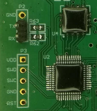
stm32-swd-blob.jpg

For me, this whole adventure started when I got non-working sensor which had swd header and blob over chip. This was not my first swd experiment. Thanks to great Hackaday Remoticon 2020 The Hackers Guide to Hardware Debugging by Matthew Alt I had already tried to connect using swd from Raspberry Pi to bluepill (which is stm32f103) so I had some experience with that. Now I also had unknown device so I can try what I can do with it.

For a start, you can notice that device have UART TX and RX pins already soldered, so first step was to connect normal 3.3V serial to those pins and see if we have some output. And I did. I could see that it's contacting sensor chip and trying to initiate NBIoT connection, but fails. So next step was to solder SWD pins, and connect them to Raspberry Pi. For that, I created openocd configuration rpi4-zc-swd.cfg and uncommeted bottom of configuration to get first idea what chip is on the board (since it's covered with blob):

swd newdap chip cpu -enable
dap create chip.dap -chain-position chip.cpu
target create chip.cpu cortex_m -dap chip.dap
init
dap info
I did made some assumptions where, for example that chip is cortex_m, but since it has swd header, there was a good chance it was.

However, since this sensor tries to get measurements in some configurable interval, just connecting using openocd didn't work since sensor after power up and sensor check went into sleep. While I could re-plug sensor repeatably, this is not needed since there is also rst pin (connected to pin 22 on Raspberry pi) which we can toggle from shell using:

raspi-gpio set 22 op
raspi-gpio get 22
raspi-gpio set 22 dl
raspi-gpio get 22
raspi-gpio set 22 dh
raspi-gpio get 22
This woke up sensor again, and I was able to connect to it using openocd and was greeted with following output:
root@rpi4:/home/pi/openocd-rpi2-stm32# openocd -f rpi4-zc-swd.cfg
Open On-Chip Debugger 0.11.0+dev-00062-g6405d35f3-dirty (2021-03-27-16:05)
Licensed under GNU GPL v2
For bug reports, read
        http://openocd.org/doc/doxygen/bugs.html
Info : BCM2835 GPIO JTAG/SWD bitbang driver
Info : clock speed 100 kHz
Info : SWD DPIDR 0x0bc11477
Info : chip.cpu: hardware has 4 breakpoints, 2 watchpoints
Info : starting gdb server for chip.cpu on 3333
Info : Listening on port 3333 for gdb connections
AP ID register 0x04770031
        Type is MEM-AP AHB3
MEM-AP BASE 0xf0000003
        Valid ROM table present
                Component base address 0xf0000000
                Peripheral ID 0x00000a0447
                Designer is 0x0a0, STMicroelectronics
                Part is 0x447, Unrecognized
                Component class is 0x1, ROM table
                MEMTYPE system memory present on bus
So, indeed this was STMicroelectronics chip, but unknown model. However, using Info : SWD DPIDR 0x0bc11477 and googling that I figured out that it's probably STM32L0xx which again made sense.

So I started openocd -f rpi4-zc-swd.cfg -f target/stm32l0_dual_bank.cfg and telnet 4444 to connect to it and I was able to dump flash. However, I had to be quick since sensor will power off itself after 30 seconds or so. Solution was easy, I toggled again rst pin and connected using gdb which stopped cpu and left sensor powered on.

However, all was not good since quick view into 64K dump showed that at end of it there was partial AT command, so dump was not whole. So I opened STM32L0x1 page and since mcu was LQFP 48 with 128k my mcu was STM32L081CB. So I restarted openocd -f rpi4-zc-swd.cfg -f target/stm32l0_dual_bank.cfg and got two flash banks:

> flash banks
#0 : stm32l0.flash (stm32lx) at 0x08000000, size 0x00010000, buswidth 0, chipwidth 0
#1 : stm32l0.flash1 (stm32lx) at 0x08010000, size 0x00010000, buswidth 0, chipwidth 0
So I was able to dump them both and got full firmware. It was also very useful, because at one point I did write flash in gdb instead in telnet 4444 connection and erased one of sensors which I was able to recover using dump which I obtained.

This however, produced another question for me: since flash is same on all sensors, where are setting which can be configured in sensor (and wasn't changed by re-flashing firmware). Since chip also has 6k of eeprom this was logical place to put it. However, openocd doesn't have bult-in support to dump eeprom from those chips. However, I did found post Flashing STM32L15X EEPROM with STLink under Linux which modified openocd to support reading and writing of eeprom back in 2015 but is not part of upstream openocd.

I didn't want to return to openocd from 2015 or port changes to current version, but I didn't have to. Since I was only interested in dumping eeprom I was able to dump it using normal mdw command:

> mdw 0x08080000 1536
1536 is number of 32-bit words in 6k eeprom (1536 * 4 = 6144). And indeed setting which are configurable where stored in eeprom.

This was fun journey into openocd and stm32, so I hope this will help someone to get started. All configuration files are available at https://github.com/dpavlin/openocd-rpi2-stm32.

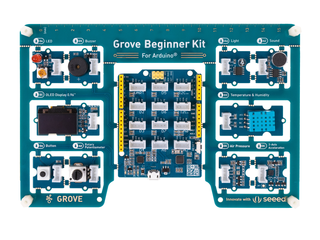
grove-beginer-kit-for-arduino.png Several months ago, I got Grove Beginner Kit For Arduino for review. I wanted to see if this board would be good fit for my friends which aren't into electronics to get them started with it.

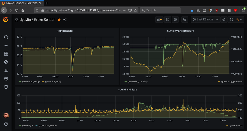
So, I started with general idea: collect values from sensors, send them to InfluxDB and create graphs using Grafana. In my opinion, showing graphs of values from real world is good way to get started with something which is not possible without little bit of additional hardware, and might be good first project for people who didn't get to try Arduino platform until now.

Kit is somewhat special: out of the box, it comes as single board with all sensors already attached, so to start using it, you just need to connect it to any usb port (it even comes with usb cable for that purpose). It also has plastic stand-offs which will provide isolation of bottom side from surface on which it's placed.

It provides following sensors on board:

ModulesInterfacePins/Address
LED Digital D4
Buzzer Digital D5
OLEDDisplay 0.96" I2C I2C, 0x78(default)
ButtonDigital D6
Rotary Potentiometer Analog A0
LightAnalog A6
SoundAnalog A2
Temperature & Humidity SensorDigital D3
Air Pressure Sensor I2C I2C, 0x77(default) / 0x76(optional)
3-Axis Accelerator I2C I2C, 0x19(default)

So I decided to show temperature, humidity, pressure, light and sound. I also added ability to show measurements on built-in oled display if you press button. Why the button press? In my experience, oled displays are prone to burn-in, and since main usage of this sensor board will be sending data to the cloud, it would be wasteful to destroy oled display which won't be used most of the time.

Programming Arduino sketch was easy using Groove Kit wiki pages which nicely document everything you will need to get you started. However, I noticed that wiki suggest to use Arduino libraries which have Grove in it's name, so I was wondering why is that so. Turns out that DHT11 temperature and humidity sensor and BMP280 temperature and pressure sensor use older version of Adafruit libraries which aren't compatible with latest versions on github. So, I tested latest versions from Adafruit and they work without any problems, just like Grove version. If you are already have them installed, there is no need to install additional Grove versions.

If you deploy sensor like this (probably connected to small Linux single board computer) it would be useful if it would be possible to update software on it witout need to run full Arduino IDE (and keyboard and mouse), so I decided to write a Makefile which uses and installs arduino-cli which is go re-implementation of support which is available in Arduino IDE, but written in go that enables usage from command-line (over ssh for example).

grove-grafana.png

So if you are interested in trying this out, and want to get graphs similar to one above, go to GroveSensor github repository clone it to your Raspberry Pi, issue make to build it and make upload to send it to your board. You will also need to edit influx.sh to point it to your InfluxDB instance, and you can start creating graphs in Grafana. All this will also work on other platforms (like x86, amd64 or aarm64) thanks to arduino-cli install script.

I must admit that Linux administration is getting better with years. I was configuring IPMI serial console on old machines (but with recent Debian) so I decided to find out which is optimal way to configure serial console using systemd.

First, let's inspect ipmi and check it's configuration to figure out baud-rate for serial port:

root@lib10:~# ipmitool sol info 1
Info: SOL parameter 'Payload Channel (7)' not supported - defaulting to 0x01
Set in progress                 : set-complete
Enabled                         : true
Force Encryption                : true
Force Authentication            : false
Privilege Level                 : ADMINISTRATOR
Character Accumulate Level (ms) : 50
Character Send Threshold        : 220
Retry Count                     : 7
Retry Interval (ms)             : 1000
Volatile Bit Rate (kbps)        : 57.6
Non-Volatile Bit Rate (kbps)    : 57.6
Payload Channel                 : 1 (0x01)
Payload Port                    : 623
Notice that there is 1 after info. This is serial port which is sol console. If you run ipmitool without this parameter or with zero, you will get error:
root@alfa:~# ipmitool sol info 0
Error requesting SOL parameter 'Set In Progress (0)': Invalid data field in request
Don't panic! There is ipmi sol console, but on ttyS1!

To configure serial console for Linux kernel we need to add something like console=ttyS1,57600 to kernel command-line in grub, and configuring correct serial port and speed:

GRUB_TERMINAL=serial
GRUB_SERIAL_COMMAND="serial --speed=57600 --unit=1 --word=8 --parity=no --stop=1"
All required changes to default configuration are below:
root@lib10:/etc# git diff
diff --git a/default/grub b/default/grub
index b8a096d..2b855fb 100644
--- a/default/grub
+++ b/default/grub
@@ -6,7 +6,8 @@
 GRUB_DEFAULT=0
 GRUB_TIMEOUT=5
 GRUB_DISTRIBUTOR=`lsb_release -i -s 2< /dev/null || echo Debian`
-GRUB_CMDLINE_LINUX_DEFAULT="boot=zfs rpool=lib10 bootfs=lib10/ROOT/debian-1"
+# serial console speed from ipmitool sol info 1
+GRUB_CMDLINE_LINUX_DEFAULT="console=ttyS1,57600 root=ZFS=lib10/ROOT/debian-1"
 GRUB_CMDLINE_LINUX=""

 # Uncomment to enable BadRAM filtering, modify to suit your needs
@@ -16,6 +17,8 @@ GRUB_CMDLINE_LINUX=""

 # Uncomment to disable graphical terminal (grub-pc only)
 #GRUB_TERMINAL=console
+GRUB_TERMINAL=serial
+GRUB_SERIAL_COMMAND="serial --speed=57600 --unit=1 --word=8 --parity=no --stop=1"

 # The resolution used on graphical terminal
 # note that you can use only modes which your graphic card supports via VBE
So in the end, there is noting to configure on systemd side. If you want to know why, read man 8 systemd-getty-generator

This year on DORS/CLUC 2018 I decided to talk about device tree in Linux kernel, so here are blurb, presentation and video of that lecture.

You have one of those fruity *Pi arm boards and cheep sensor from China? Some buttons and LEDs? Do I really need to learn whole new scripting language and few web technologies to read my temperature, blink a led or toggle a relay?
No, because your Linux kernel already has drivers for them and all you need is device tree and cat.

IMG_20140616_091523.jpg

Every year, our three day annual DORS/CLUC 2014 conference is happening. This year, the dates shifted a few weeks later, which resulted in less students showing up because of exams, so it was a somewhat different experience than years before. For few years now we are not at the University of Zagreb, FER location so it also changed conference a bit. Having said that, even after move from FER, we still had a bus of students from my own faculty FOI in Varaždin, and they where missing this year.

It was still full conference in new (2nd floor, not ideal for breaks in fresh air which is a must to stay for 11 hours each day, mind you) location at Croatian Chamber of Economy new and nice conference hall with wifi which was stable but didn't allow UDP traffic. Both mosh and n2n didn't work for me.

It was also in very different format. I would love to know did it worked for people or not. Instead of charging for workshops, they where included in conference price, and as every year, it you where interested in topic, nobody will turn you away from workshop because of space :-) This also meant that workshops are three hours slots at the end of the day after 7 hours of lectures. When conference started, we where afraid how will we accommodate all that people at workshops, but sense prevailed and about 20 or so people stayed for workshop each day.

Parallella and Epiphany 16 core mesh CPU

presentation

I had 5-minute lightning talk about Parallella, and hopefully managed to explain, that there is now interesting dual-core ARM, with interesting DSP-like capabilities backed by OpenCL and FPGA. This is unique combination of processing power, and it would be interesting to see which part of this machine can run OpenVPN encryption best for example, because it has 1Gbit/s ethernet interface.

ZFS workshop, updated to 0.6.3

presentation

ZFS on Linux had a 0.6.3 release just in time, and I presented two and half hour long workshop about ZFS for which 10-20 people stayed, after 7 ours of presentations. I somewhat field to show enough in command-line, I'm afraid, because I was typing too little. I did managed to show what will you get if you re-purpose several year old hardware for ZFS storage. Something along lines of 2004 year hardware with 8 SCSI disks.

I managed to create raid-10 like setup, but with all benefits of ZFS, fill it up and scrub it during workshop.

root@debian:/workshop# zfs list
NAME                  USED  AVAIL  REFER  MOUNTPOINT
workshop              268G    28K   268G  /workshop
workshop/test1        280K    28K   144K  /workshop/test1
workshop/test1/sub1   136K    28K   136K  /workshop/test1/sub1
root@debian:/workshop# zpool status
  pool: workshop
 state: ONLINE
  scan: scrub repaired 0 in 0h44m with 0 errors on Tue Jun 17 17:30:38 2014
config:

        NAME                                      STATE     READ WRITE CKSUM
        workshop                                  ONLINE       0     0     0
          mirror-0                                ONLINE       0     0     0
            scsi-SFUJITSU_MAS3735NC_A107P4B02KAT  ONLINE       0     0     0
            scsi-SFUJITSU_MAS3735NC_A107P4B02KBB  ONLINE       0     0     0
          mirror-1                                ONLINE       0     0     0
            scsi-SFUJITSU_MAS3735NC_A107P4B02KCK  ONLINE       0     0     0
            scsi-SFUJITSU_MAS3735NC_A107P4B02KDD  ONLINE       0     0     0
          mirror-2                                ONLINE       0     0     0
            scsi-SFUJITSU_MAS3735NC_A107P4B02L4S  ONLINE       0     0     0
            scsi-SFUJITSU_MAS3735NC_A107P4B02L4U  ONLINE       0     0     0
          mirror-3                                ONLINE       0     0     0
            scsi-SFUJITSU_MAW3073NC_DAL3P6C04079  ONLINE       0     0     0
            scsi-SFUJITSU_MAW3073NC_DAL3P6C040BM  ONLINE       0     0     0

errors: No known data errors
I think it might be good idea to pxeboot this machine on demand (for long-term archival storage) and copy snapshots to it on weekly basis for example. Think of it as tape alternative (quite small, 300G) but with rather fast random IO. Idea was to use this setup for ganeti-backup target, but dump format of ext file-system forced us to use zfs volumes to restore backup on other RAIDZ1 4*1.5T SATA pool, and it was very slow.
In current state, it can receive zfs snapshots at 30-40 MB/s and it's using single core for ssh, which is bottleneck. More benchmarks have to be done on this machine to see weather it's worth electricity it's using...

Ganeti - our own cloud

presentation

Another interesting part of infrastructure work last year for me was with Luka Blašković. We migrated all servers from faculty and library to two Ganeti groups. We are running cluster of reasonable size (10+ nodes, 70+ instances). Everything we did is done from legacy hardware which is now much better utilized. Some machines where never backuped and firmware upgraded so it was first time for them to have this kind of maintenance in last 10 years. Now we can move VM instances to another machine, and we are much more confident that services will stay running via live migration for scheduled maintenance or restart in case of hardware failure.

For workshop, we decided to chew a bit more than we can swallow. We spun up KVM images on our ganeti cluster and went through installation of workshop ganeti on them and joining them to new cluster. This went fairly well, but then we started configuring xen to spawn new instances (ganeti kvm with ganeti xen on top of it) we had some problems with memory limits which we managed to fix before end of workshop.
In our defense, we really believe that workshop was more interesting this way, probably because people didn't want to leave (few brave ones which where with us all the way to the end, that is). When you try to deploy something as complex as Ganeti you will run into some problems, so seeing troubleshooting methods used is usually as helpful as solution itself.

All in all, it was interesting and very involved three days. Hope to see you all again next year.

As you know by now, few months ago I built 433 MHz control of power sockets using rc-switch. Since then, I somehow lost remote control for it so I decided to have more permanent solution than bunch of wires. This time around I also used USBee AX Pro clone to check voltage levels which meant that I first had to make it work on Linux.

IMG_20131215_184439.jpg

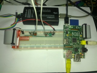
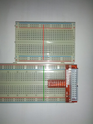
You can see final result on picture included in this post. It was mixed experience which included few surprises which might be useful to other people doing hacking with Raspberry Pi, so I decided to write this post. As I'm somewhat cheap, I didn't want to buy Adafruit Pi Cobbler but instead went with Raspberry Pi GPIO adapter board module which has additional benefit of routing 5V and 3.3V to power rails on breadboard. I already had 26 pin cable, but if you don't have one, make sure you get that also. Breakout board also have markings for wiringPi (as opposed to one of other variants of GPIO pins on pi). When breakout board arrived I noticed something interesting: it requires power pins which are aligned with holes on main board. Examine picture below to see difference.

breadboard-power-pins-aligment.jpg

As you can see on top 400 point breadboard, power pins are in the middle pins of main area which means that you won't be able to plug in breakout board into power rails. I was fortunate enough that another 800 point breadboard had power pins aligned with main area, but none of smaller 400 point breadboards I have are correctly aligned. Picture on seller's site does show 400 point breadboard, but adapter board shows V2.0 while mine is V2.2, but judging from picture 400 point breadboards with aligned pins do exist.

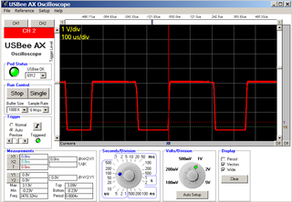
This time around, I also received USB Oscilloscope and logic analyzer which includes two analog ports which is clone of USBee AX Pro so I decided to see signals which receiver generated using it and picture is included below.

RF443-scope.PNG

As you can see, I was forced to use Windows XP in virtual machine to make it work. Although there is free software support for logic analyzer part of it in sigrok developers aren't really excited with USBee AX Pro clones so support for analog channels is missing. There is code in ax branch, but I haven't had a chance to try it yet. For few months I thought that it doesn't work at all, mostly because I was trying to make it work in kvm and VirtualBox. Finally, a friend suggested to try vmware, and it worked without a problem. Since there is open source implementation of USBee SX protocol, I think it's quite possible to extend it to support analog ports on AX Pro, but I haven't had time to do this yet. Have in mind that buying USBee Test Pod clones is not something CWAV condones, and newer versions of software from their's web site will re-flash the device (original is read only) which will make it unusable. DX has a long thread with dead links to Cypress site how to fix this, but easiest solution I found so far was to go to site of another clone called ESLA201A and download fix_esla201.rar which includes everything you need to re-flash USB ID back to USBee AX Pro in single rar archive.

When you are trying to configure touch screen on Linux machine, internet offers examples Xorg.conf configuration but without explanation were numbers in it came from. If you have different touch screen you might be out of luck or guess what to do. In this post, I will try to explain how to examine your device using evtest and try out settings using xinput without restarting X server or installing any drivers other than built-in evdev.

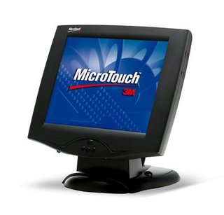
microtouch.jpg

We have a couple of 3M MicroTouch M150 touch screens which are VGA monitors (1024*768 resolution) with USB touchscreen interface which is reported as:

dpavlin@t42:~$ lsusb -d 0596:0001
Bus 002 Device 002: ID 0596:0001 MicroTouch Systems, Inc. Touchscreen
A bit of googling later, I found out that there are two different drivers for microtouch devices, but both of them support serial devices only. Not giving up that easily I decided to see what xinput reports about it (without any additional drivers installed!):
dpavlin@t42:~$ xinput list
⎡ Virtual core pointer                          id=2    [master pointer  (3)]
⎜   ↳ Virtual core XTEST pointer                id=4    [slave  pointer  (2)]
⎜   ↳ 3M 3M USB Touchscreen - EX II             id=9    [slave  pointer  (2)]
⎜   ↳ SynPS/2 Synaptics TouchPad                id=11   [slave  pointer  (2)]
⎜   ↳ TPPS/2 IBM TrackPoint                     id=12   [slave  pointer  (2)]
⎣ Virtual core keyboard                         id=3    [master keyboard (2)]
    ↳ Virtual core XTEST keyboard               id=5    [slave  keyboard (3)]
    ↳ Power Button                              id=6    [slave  keyboard (3)]
    ↳ Video Bus                                 id=7    [slave  keyboard (3)]
    ↳ Sleep Button                              id=8    [slave  keyboard (3)]
    ↳ AT Translated Set 2 keyboard              id=10   [slave  keyboard (3)]
    ↳ ThinkPad Extra Buttons                    id=13   [slave  keyboard (3)]
This seems like a good news, but when I tried to use it, it seemed that cursor would move only in middle of screen (with X axis swapped) so I wasn't very happy about it. Examining properties of device in more detail revealed that it has property to swap axes and calibrate them, but what to write into those values?
dpavlin@t42:~$ xinput list-props 9
Device '3M 3M USB Touchscreen - EX II':
        Device Enabled (139):   1
        Coordinate Transformation Matrix (141): 1.000000, 0.000000, 0.000000, 0.000000, 1.000000, 0.000000, 0.000000, 0.000000, 1.000000
        Device Accel Profile (263):     0
        Device Accel Constant Deceleration (264):       1.000000
        Device Accel Adaptive Deceleration (265):       1.000000
        Device Accel Velocity Scaling (266):    10.000000
        Device Product ID (257):        1430, 1
        Device Node (258):      "/dev/input/event7"
        Evdev Axis Inversion (267):     0, 0
        Evdev Axis Calibration (268):   <no items>
        Evdev Axes Swap (269):  0
        Axis Labels (270):      "Abs X" (261), "Abs Y" (262)
        Button Labels (271):    "Button Unknown" (260), "Button Unknown" (260), "Button Unknown" (260), "Button Wheel Up" (145), "Button Wheel Down" (146)
        Evdev Middle Button Emulation (272):    0
        Evdev Middle Button Timeout (273):      50
        Evdev Third Button Emulation (274):     0
        Evdev Third Button Emulation Timeout (275):     1000
        Evdev Third Button Emulation Button (276):      3
        Evdev Third Button Emulation Threshold (277):   20
        Evdev Wheel Emulation (278):    0
        Evdev Wheel Emulation Axes (279):       0, 0, 4, 5
        Evdev Wheel Emulation Inertia (280):    10
        Evdev Wheel Emulation Timeout (281):    200
        Evdev Wheel Emulation Button (282):     4
        Evdev Drag Lock Buttons (283):  0
First task was was to flip x axes to make it move left-right instead of right-left. This can be acomplised using following command:
dpavlin@t42:~$ xinput set-prop 9 267 1 0
Parameters are device id, property id, X axis swap and Y axis swap. If you don't know how many parameters property takes, just put one, try it out and if it returns errors, keep adding parameters until it suceeds.

Next, I needed to calibrate screen to track my finger moving over surface. This is where evtest comes into play. It's low level utility which enables you to see input events before they are passwd to Xorg server. You will have to run it as root as follows:

dpavlin@t42:~$ sudo evtest
No device specified, trying to scan all of /dev/input/event*
Available devices:
/dev/input/event0:      AT Translated Set 2 keyboard
/dev/input/event1:      Lid Switch
/dev/input/event2:      Sleep Button
/dev/input/event3:      Power Button
/dev/input/event4:      ThinkPad Extra Buttons
/dev/input/event5:      Video Bus
/dev/input/event6:      PC Speaker
/dev/input/event7:      3M 3M USB Touchscreen - EX II
/dev/input/event8:      SynPS/2 Synaptics TouchPad
/dev/input/event9:      TPPS/2 IBM TrackPoint
Select the device event number [0-9]: 7
Input driver version is 1.0.1
Input device ID: bus 0x3 vendor 0x596 product 0x1 version 0x410
Input device name: "3M 3M USB Touchscreen - EX II"
Supported events:
  Event type 0 (EV_SYN)
  Event type 1 (EV_KEY)
    Event code 330 (BTN_TOUCH)
  Event type 3 (EV_ABS)
    Event code 0 (ABS_X)
      Value   7353
      Min        0
      Max    16384
    Event code 1 (ABS_Y)
      Value   4717
      Min        0
      Max    16384
Properties:
Testing ... (interrupt to exit)
Immidiatly we can see minimum and maximum values for both axes and putting figer on top-left corner of screen produced (a lot of) output like this:
Event: time 1386078786.506710, -------------- SYN_REPORT ------------
Event: time 1386078786.510712, type 3 (EV_ABS), code 0 (ABS_X), value 13919
Event: time 1386078786.510712, type 3 (EV_ABS), code 1 (ABS_Y), value 2782
After a few touches I had coordinates which where something like this:
14046,27222380,2986
7994,7819
13743,136162624,13545
Strangly it seems that origin is top-right corner, but we shouldn't care much about it beacuse we can specify them using following command (after rounding them a bit):
dpavlin@t42:~$ xinput set-prop 9 268 2380 14000 2800 13500
Trying it out on screen proved that it now works as expected. Let's call this success and remember that current Xorg knows a lot of tricks itself (recognising USB touch devices is one of them).

As a side note you don't really need to use evtest to get device position. Using xinput list id syntax displays you more-or-less same information, including last point which you touched on device as seen below:

dpavlin@t42:~$ xinput list 9
3M 3M USB Touchscreen - EX II                   id=9    [slave  pointer  (2)]
        Reporting 3 classes:
                Class originated from: 9. Type: XIButtonClass
                Buttons supported: 5
                Button labels: "Button Unknown" "Button Unknown" "Button Unknown" "Button Wheel Up" "Button Wheel Down"
                Button state:
                Class originated from: 9. Type: XIValuatorClass
                Detail for Valuator 0:
                  Label: Abs X
                  Range: 0.000000 - 16384.000000
                  Resolution: 0 units/m
                  Mode: absolute
                  Current value: 13889.000000
                Class originated from: 9. Type: XIValuatorClass
                Detail for Valuator 1:
                  Label: Abs Y
                  Range: 0.000000 - 16384.000000
                  Resolution: 0 units/m
                  Mode: absolute
                  Current value: 2832.000000
However evtest will run in loop until you stop it with Ctrl+C so I find it a little bit easier to use than re-running xinput list id.