Results matching “search”

I know that it's 2021, but we are still having problems with encoding in mysql (MariaDB in this cane, but problem is smilar). This time, it's application which I inherited which saves utf-8 data into database which is declared as latin1.

How can you check if this is problem with your database too?

MariaDB [ompdb]> show create database ompdb ;
+----------+------------------------------------------------------------------+
| Database | Create Database                                                  |
+----------+------------------------------------------------------------------+
| ompdb    | CREATE DATABASE `ompdb` /*!40100 DEFAULT CHARACTER SET latin1 */ |
+----------+------------------------------------------------------------------+
Alternative way is to invoke mysqldump ompdb and example file generated. Why is this a problem? If we try SQL query on one of tables:
MariaDB [ompdb]> select * from submission_search_keyword_list where keyword_text like 'al%ir' ;
+------------+--------------+
| keyword_id | keyword_text |
+------------+--------------+
|       3657 | alzir        |
|       1427 | alžir       |
+------------+--------------+
You can clearly see double-encoded utf8 which should be alžir. This is because our client is connecting using utf8 charset, getting utf8 data in binary form so we see double-encoding. So we can try to conntect using latin1 with:
root@omp-clone:/home/dpavlin# mysql --default-character-set=latin1 ompdb
MariaDB [ompdb]> select * from submission_search_keyword_list where keyword_text like 'al%ir' ;
+------------+--------------+
| keyword_id | keyword_text |
+------------+--------------+
|       3657 | alzir        |
|       1427 | alžir       |
+------------+--------------+
Note that everything is still not well, because grid after our utf8 data is not aligned well.

Googling around, you might find that possible solution is to add --default-character-set=latin1 to mysqldump, edit all occurrences of latin1 to utf8 (utf8mb4 is better choice) and reload database, and problem is solved, right?

If we try to do that, we will get following error:

ERROR 1062 (23000) at line 1055 in file: '1.sql': Duplicate entry 'alžir' for key 'submission_search_keyword_text'
Why is this? MySQL uses collation setting to remove accents from data, so it treats alzir and alžir as same string. Since we have both of them in our data, this is not good enough. Also, editing database manually always makes me nervous, so we will using following to get database dump without declaration of encoding (due to --skip-opt option), but using latin1 for dumping data:
mysqldump ompdb --skip-set-charset --default-character-set=latin1 --skip-opt > /tmp/1.sql
Next, we need to create database with collation which preserves everything (utf8mb4_bin) using:
CREATE DATABASE omp2 CHARACTER SET = 'utf8mb4' COLLATE 'utf8mb4_bin' ;
Finally we should be able to reload created dump without errors:
mysql omp2 < /tmp/1.sql

One additional benefit of using --skip-opt for mysqldump is that every insert is split into individual line. So if you want to have correct collation and skip data which is invalid (which might be possible depending on where data is) you can use same mysqldump file and add -f flag when reloading dump like mysql -f omp2 < /tmp/1.sql which will report data that have errors, but insert everything else into database.

We have been using request tracker for years but recently changed how many e-mail addresses we keep in LDAP mail attribute. Up until now, we stored just our local e-mail addresses there, but lately we also added external addresses that our users have.

This created a problem when users try to send e-mail from external address to our rt. To test this, I have account usertest which has dpavlin@example.com as first mail in LDAP and dpavlin@m.example.com as second one and I'm sending e-mail from dpavlin@m.example.com like this:

swaks --to sysadmin@rt.example.com --from dpavlin@m.example.com
Result is following log which seems very verbose, but is also useful in understanding what is going wrong:


[14188] [Fri Apr 16 07:57:26 2021] [debug]: Going to create user with address 'dpavlin@m.example.com' (/usr/local/share/request-tracker4/lib/RT/Interface/Email/Auth/MailFrom.pm:100)
[14188] [Fri Apr 16 07:57:26 2021] [debug]: RT::Authen::ExternalAuth::CanonicalizeUserInfo called by RT::Authen::ExternalAuth /usr/local/share/request-tracker4/plugins/RT-Authen-ExternalAuth/lib/RT/Authen/ExternalAuth.pm 886 with: Comments: Autocreated on ticket submission, Disabled: , EmailAddress: dpavlin@m.example.com, Name: dpavlin@m.example.com, Password: , Privileged: , RealName: (/usr/local/share/request-tracker4/plugins/RT-Authen-ExternalAuth/lib/RT/Authen/ExternalAuth.pm:793)
[14188] [Fri Apr 16 07:57:26 2021] [debug]: Attempting to get user info using this external service: FFZG_LDAP (/usr/local/share/request-tracker4/plugins/RT-Authen-ExternalAuth/lib/RT/Authen/ExternalAuth.pm:801) [14188] [Fri Apr 16 07:57:26 2021] [debug]: Attempting to use this canonicalization key: Name (/usr/local/share/request-tracker4/plugins/RT-Authen-ExternalAuth/lib/RT/Authen/ExternalAuth.pm:810)
[14188] [Fri Apr 16 07:57:26 2021] [debug]: LDAP Search === Base: dc=ffzg,dc=hr == Filter: (&(objectClass=*)(uid=dpavlin@m.example.com)) == Attrs: co,uid,postalCode,physicalDeliveryOfficeName,uid,streetAddress,telephoneNumber,hrEduPersonUniqueID,cn,l,st,mail (/usr/local/share/request-tracker4/plugins/RT-Authen-ExternalAuth/lib/RT/Authen/ExternalAuth/LDAP.pm:358)
[14188] [Fri Apr 16 07:57:26 2021] [debug]: Attempting to use this canonicalization key: EmailAddress (/usr/local/share/request-tracker4/plugins/RT-Authen-ExternalAuth/lib/RT/Authen/ExternalAuth.pm:810)
[14188] [Fri Apr 16 07:57:26 2021] [debug]: LDAP Search === Base: dc=ffzg,dc=hr == Filter: (&(objectClass=*)(mail=dpavlin@m.example.com)) == Attrs: co,uid,postalCode,physicalDeliveryOfficeName,uid,streetAddress,telephoneNumber,hrEduPersonUniqueID,cn,l,st,mail (/usr/local/share/request-tracker4/plugins/RT-Authen-ExternalAuth/lib/RT/Authen/ExternalAuth/LDAP.pm:358)
[14188] [Fri Apr 16 07:57:26 2021] [info]: RT::Authen::ExternalAuth::CanonicalizeUserInfo returning Address1: , City: Zagreb, Comments: Autocreated on ticket submission, Country: , Disabled: , EmailAddress: dpavlin@example.com, ExternalAuthId: usertest@example.com, Gecos: usertest, Name: usertest, Organization: , Password: , Privileged: , RealName: Testičić Probišić Đž, State: , WorkPhone: 014092209, Zip: (/usr/local/share/request-tracker4/plugins/RT-Authen-ExternalAuth/lib/RT/Authen/ExternalAuth.pm:869)
[14188] [Fri Apr 16 07:57:26 2021] [crit]: User could not be created: User creation failed in mailgateway: Name in use (/usr/local/share/request-tracker4/lib/RT/Interface/Email.pm:243)
[14188] [Fri Apr 16 07:57:26 2021] [warning]: Couldn't load user 'dpavlin@m.example.com'.giving up (/usr/local/share/request-tracker4/lib/RT/Interface/Email.pm:876)
[14188] [Fri Apr 16 07:57:26 2021] [crit]: User could not be loaded: User 'dpavlin@m.example.com' could not be loaded in the mail gateway (/usr/local/share/request-tracker4/lib/RT/Interface/Email.pm:243)
[14188] [Fri Apr 16 07:57:26 2021] [error]: Could not load a valid user: RT could not load a valid user, and RT's configuration does not allow for the creation of a new user for this email (dpavlin@m.example.com). You might need to grant 'Everyone' the right 'CreateTicket' for the queue SysAdmin. (/usr/local/share/request-tracker4/lib/RT/Interface/Email.pm:243)

I'm aware that lines are long, and full of data but they describe problem quite well:

  1. RT tries to find user with e-mail address dpavlin@m.example.com (which doesn't exist since RT uses just first e-mail from LDAP which is dpavlin@example.com)
  2. then it tries to create new user with dpavlin@m.example.com, but runs another search over ldap to make sure it won't create duplicate user
  3. this will find user in ldap due to second email adress and gives wrong error message.
As log file is very detailed and include path to files used and line numbers solution was simple additional check for this exact case:
--- /usr/share/request-tracker4/plugins/RT-Authen-ExternalAuth/lib/RT/Authen/ExternalAuth/LDAP.pm.orig  2017-04-05 14:57:22.932000146 +0200
+++ /usr/share/request-tracker4/plugins/RT-Authen-ExternalAuth/lib/RT/Authen/ExternalAuth/LDAP.pm       2021-04-16 15:49:34.800001819 +0200
@@ -429,6 +429,12 @@
                                 $ldap_msg->code);
     }

+    # FIXME -- dpavlin 2021-04-16 -- check if e-mail from ldap is same as incomming one
+    if ( $key eq 'mail' && $value ne $params{EmailAddress}) {
+       $RT::Logger->debug( "LDAP mail check return not found key = $key value = $value $params{EmailAddress}");
+       $found = 0;
+    }
+
     undef $ldap;
     undef $ldap_msg;

If e-mail address we found in LDAP is not the same one we did lookup on in CanonicalizeUserInfo we just ignore it.

I think that nicely shows power of good logs and open source software written in scripting language which you can modify in the place for your (slightly broken) configuration.

If you ever needed to connect to JTAG or SWD on stm32 and tried to search for solutions on Internet, you quickly realized that amount of information is overwhelming. However, fear not. If you have Raspberry Pi and few wires, you are already half-way there.

stm32-swd-blob.jpg

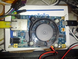
For me, this whole adventure started when I got non-working sensor which had swd header and blob over chip. This was not my first swd experiment. Thanks to great Hackaday Remoticon 2020 The Hackers Guide to Hardware Debugging by Matthew Alt I had already tried to connect using swd from Raspberry Pi to bluepill (which is stm32f103) so I had some experience with that. Now I also had unknown device so I can try what I can do with it.

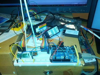
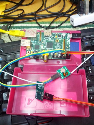
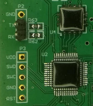
For a start, you can notice that device have UART TX and RX pins already soldered, so first step was to connect normal 3.3V serial to those pins and see if we have some output. And I did. I could see that it's contacting sensor chip and trying to initiate NBIoT connection, but fails. So next step was to solder SWD pins, and connect them to Raspberry Pi. For that, I created openocd configuration rpi4-zc-swd.cfg and uncommeted bottom of configuration to get first idea what chip is on the board (since it's covered with blob):

swd newdap chip cpu -enable
dap create chip.dap -chain-position chip.cpu
target create chip.cpu cortex_m -dap chip.dap
init
dap info
I did made some assumptions where, for example that chip is cortex_m, but since it has swd header, there was a good chance it was.

However, since this sensor tries to get measurements in some configurable interval, just connecting using openocd didn't work since sensor after power up and sensor check went into sleep. While I could re-plug sensor repeatably, this is not needed since there is also rst pin (connected to pin 22 on Raspberry pi) which we can toggle from shell using:

raspi-gpio set 22 op
raspi-gpio get 22
raspi-gpio set 22 dl
raspi-gpio get 22
raspi-gpio set 22 dh
raspi-gpio get 22
This woke up sensor again, and I was able to connect to it using openocd and was greeted with following output:
root@rpi4:/home/pi/openocd-rpi2-stm32# openocd -f rpi4-zc-swd.cfg
Open On-Chip Debugger 0.11.0+dev-00062-g6405d35f3-dirty (2021-03-27-16:05)
Licensed under GNU GPL v2
For bug reports, read
        http://openocd.org/doc/doxygen/bugs.html
Info : BCM2835 GPIO JTAG/SWD bitbang driver
Info : clock speed 100 kHz
Info : SWD DPIDR 0x0bc11477
Info : chip.cpu: hardware has 4 breakpoints, 2 watchpoints
Info : starting gdb server for chip.cpu on 3333
Info : Listening on port 3333 for gdb connections
AP ID register 0x04770031
        Type is MEM-AP AHB3
MEM-AP BASE 0xf0000003
        Valid ROM table present
                Component base address 0xf0000000
                Peripheral ID 0x00000a0447
                Designer is 0x0a0, STMicroelectronics
                Part is 0x447, Unrecognized
                Component class is 0x1, ROM table
                MEMTYPE system memory present on bus
So, indeed this was STMicroelectronics chip, but unknown model. However, using Info : SWD DPIDR 0x0bc11477 and googling that I figured out that it's probably STM32L0xx which again made sense.

So I started openocd -f rpi4-zc-swd.cfg -f target/stm32l0_dual_bank.cfg and telnet 4444 to connect to it and I was able to dump flash. However, I had to be quick since sensor will power off itself after 30 seconds or so. Solution was easy, I toggled again rst pin and connected using gdb which stopped cpu and left sensor powered on.

However, all was not good since quick view into 64K dump showed that at end of it there was partial AT command, so dump was not whole. So I opened STM32L0x1 page and since mcu was LQFP 48 with 128k my mcu was STM32L081CB. So I restarted openocd -f rpi4-zc-swd.cfg -f target/stm32l0_dual_bank.cfg and got two flash banks:

> flash banks
#0 : stm32l0.flash (stm32lx) at 0x08000000, size 0x00010000, buswidth 0, chipwidth 0
#1 : stm32l0.flash1 (stm32lx) at 0x08010000, size 0x00010000, buswidth 0, chipwidth 0
So I was able to dump them both and got full firmware. It was also very useful, because at one point I did write flash in gdb instead in telnet 4444 connection and erased one of sensors which I was able to recover using dump which I obtained.

This however, produced another question for me: since flash is same on all sensors, where are setting which can be configured in sensor (and wasn't changed by re-flashing firmware). Since chip also has 6k of eeprom this was logical place to put it. However, openocd doesn't have bult-in support to dump eeprom from those chips. However, I did found post Flashing STM32L15X EEPROM with STLink under Linux which modified openocd to support reading and writing of eeprom back in 2015 but is not part of upstream openocd.

I didn't want to return to openocd from 2015 or port changes to current version, but I didn't have to. Since I was only interested in dumping eeprom I was able to dump it using normal mdw command:

> mdw 0x08080000 1536
1536 is number of 32-bit words in 6k eeprom (1536 * 4 = 6144). And indeed setting which are configurable where stored in eeprom.

This was fun journey into openocd and stm32, so I hope this will help someone to get started. All configuration files are available at https://github.com/dpavlin/openocd-rpi2-stm32.

This year on DORS/CLUC 2018 I decided to talk about device tree in Linux kernel, so here are blurb, presentation and video of that lecture.

You have one of those fruity *Pi arm boards and cheep sensor from China? Some buttons and LEDs? Do I really need to learn whole new scripting language and few web technologies to read my temperature, blink a led or toggle a relay?
No, because your Linux kernel already has drivers for them and all you need is device tree and cat.

hantek-dso-2090.jpg

I have been using Hantek DSO-2090 USB oscilloscope for more than half a year now. While scope purist will say that usb oscilloscopes are not good enough for serious use for my use it's quite sufficient. However, this weekend, I was reverse engineering CPLD with R2R digital to analog converter, and I needed to figure out which steps are produced by turning pins on CPLD on or off. Sure, I can use multi-meter to do this, but if I already have oscilloscope it's much more powerful tool for task like this.

When choosing USB oscilloscope, I searched a lot, and decided to buy Hantek DSO-2090 because it's supported by free software like OpenHantek and sigrok. There are better oscilloscopes out there, but this one is supported by free software, and there is even a detailed tear-down which explains how to increase it's performance. When scope arrived, I was quite pleased with OpenHantek, but never managed to get sigrok working with it. It didn't matter at the time, since OpenHantek had everything I needed. However, for this task at hand I really needed minimum and maximum voltage. As you can see in video describing oscilloscope usage, and especially Hantek DSO-2090, including it's limits.

openhantek.png

OpenHantek shows just amplitude of signal, which is difference between minimal and maximal voltage but doesn't show raw values which I needed. So, I wrote simple patch to OpenHantek to display minimum, amplitude and maximum voltage as you can see in picture. I also wrote a message on mailing list with a patch, so I hope you might expect to see this change in next version of OpenHantek.

IMG_20140508_110839.jpg

After 18 months Parallella kickstarter project delivered and I got the device in my hands. To be honest, I was prepared to write off $100 for it, but decided to support the project because I believe that we should have alternative architectures developed and Epiphany had such a goal.

As you can see on the picture, I got parallella board and heatsink for FPGA in nice box together with the pack slip. Heatsink is recent addition because the FPGA get very hot. However, it's not enough because you will also need some air flow over it to ensure stable operation. And 5V 2A power supply. So, I decided to do some research before the first power-on because burning board on the first try is not a good option.

Here is where Parallella forums came in very handy. It's full of very supportive community, and to learn how to use your board it's better place than the official documentation (and more up-to-date). On it you can learn that there are jumpers on the board to provide 5V for fan, and various other hints about the platform including ability to power the board over USB connector which proved helpful since I could use a 2A Nexus power supply.

Official image for Parallella is based on Ubuntu (which I don't like much, it even doesn't move devtmpfs by default), so I opted to install the unsupported Debian installation and try to lower power usage by disabling HDMI support since I'm not using it. And thanks to helpful parallella community and the forum post about with alternative parallella bitstreams and device tree I was successful in that task lowering power draw to ~0.75 A in idle mode and ~0.86 A while testing with aobench from parallella-examples. CPU load alone (two arm cores) seem to consume ~0.81 A. For comparison, HDMI bitstream consumes ~1.03 A in idle and ~1.19 A under load. All values are maximal ones which I measured using USB charger doctor, so they might not be the most precise.

IMG_20140525_130254.jpg

To cool the device, I have salvaged small fan from an old disk drawer and attached it to the board using zip ties.

Power is supplied from a USB port on PC (for now), but the next logical step is to connect it to the jumpers on board and print the case for it on 3D printer. This involves mocking up with 3D software to the design case, so it might take some time. However, so far I'm very happy with my new toy.

One of simplest home automation projects is to control power sockets. Back in the old days, this involved relays and parallel port, but nowadays you can buy ready made power sockets with remote control which work on 433 MHz IMS band. So next logical step is to replace remote control with computer controlled 433 MHz module. In this post, I will explain how to do it using Arduino or Raspberry Pi.

Power sockets with 433 MHz remote control

For this project I decided to try out two different types of power sockets available at our local hardware shop.

IMG_20130929_131622.jpg IMG_20130929_151434.jpg

As you can see they are quite different, but any of then will work fine. On the other hand, big bulky square ones have much more useful indicator on then which lights up then they are enabled, while smaller round ones have light which just denotes that they are plugged into electricity but doesn't show status of relay inside of them.

433 MHz modules

IMG_20130930_001121.jpg

If you want to communicate with these devices you will need some kind of radio modems. For this project, I decided to use cheap 433 MHz radio modules which come in pair: one of them is sender while another is receiver. On picture you can see modules with attached antenna.

I can't stress enough need for antenna. Although modules will work without it, they will have a really poor range of just few centimeters. Antenna should be 172 mm (1/4 of wavelength), and according to my friend who knows something about this things, it's equally bad to have longer or shorter antenna than that. I added 3 mm more for solder joint and it did improve reception and sending range dramatically. You can use any wire for antenna, in my case, I used wire used for wrapping power cords which was long enough to make two antennas.

Arduino

IMG_20131012_193005.jpg

As a first step, I decided to hook them to Arduino Uno to see some waveforms and test rc-switch library. Sure enough it worked on first try. I added project to my ~/Arduino/libraries/RCSwitch directory and used ReceiveDemo_Advanced example to capture signals. Another example, SendDemo enabled me to send signals back to power sockets and turn them on or off. Success on the first try.

With a little bit of tweaking I created RF433_Sockets.ino which allows receiving signals, turning sockets on or off or sending raw binary data to test protocols.

As you can see on picture, I also connected cheap logic analyzer clone to see signals and Bus pirate to monitor signal levels using Bus Pirate oscilloscope python script to make sure that I can connect it to 3.3V level device in next step and I got signals like this on receive pin: scope_2013-09-29T17:57:00.873653.png

Raspberry Pi

IMG_20131016_135743.jpg

Having verified that signal receiver is generating 3.3V signals (up to 3.6V is OK and mine is 3.46V - electronics isn't exact it seems :-), I decided to hook it up to Raspberry Pi so I will have Internet connected control over my power sockets.

Following link on rc-switch site to port for Raspberry Pi didn't end up all that well. This version of code doesn't support receiving of data, and sending code generates segfaults. However, after a little bit of searching I found blog post about Adding 433 to your Raspberry Pi from NinjaBlocks which inclues link to github repository with code which works fine.

Both versions of code use WiringPi library which is nice way to port Arduino code to Raspberry Pi. When sending signals to 5V devices 3.3V Raspberry Pi GPIO will be usually fine, but when receiving singals, make sure that they are 3.3V or you will fry your Raspberry Pi.

Less than $10 and few hours of work...

Having said all that, it's really easy to create your own home automation system. So I don't see a reason not to do so...

Parts list: (assuming you already have Arduino or Raspberry Pi)

nRF24L01 It's again this time of year when security researchers (and me) gather in Varaždin for fsec, vendor-neutral technical security symposium, hosted by Faculty of Organization and Informatics. This year, I deiced to re-visit my question about security wireless keyboards, so I ported Travis Goodspeed's GoodFET to Arduino UNO. Goal was to use cheap nRF24L01 modules from ebay to see if my Chicony KG-0609 keyboard is sniffable. And it is...

You can find the presentation in which I also tried to cover my experience with hardware hacking below.

I hope it was interesting to people who attended it, although I suspect that I crammed too much content into 30 minute slot which I had. If you are interested in my changes, they are available in Arduino_Uno branch in goodfet project at git.rot13.org.

This event has special place in my calender since I'm alumni and it's always nice to meet again friends and professors and visit again place where I started my Unix administration back in 1995. Thanks to everybody for nice three days in beautiful Varaždin.

IMG_20130908_140327.jpg

A few weeks ago my WRT54GL decided to die. This was quite fortunate because I wanted to upgrade my always on machine to something more powerful and install Debian on it. I had ADSL modem with wifi, so I didn't need wifi in my new box. Fortunately, I got a Igel 3/4 thin client with VIA Eden chipset, 256Mb of RAM and 128 Mb of CF storage so I decided to move by main gateway functions to it.

I had following requirements:

  • pppoe to connect to by ISP
  • dnsmasq to provide DHCP for my LAN
  • iptables will provide NAT
  • openvpn and n2n to provide VPN
  • motion so I can see what my dog is doing when I'm not home
As a first installation I started with Thinkpad T22 (since Igel was still on the way). All went quite well (after figuring out that I can't boot T22 from USB) but it took 2GB of disk space. That won't fit on 128MB CF card, so I acquired 2GB CF card. Still, even with it, the storage will be tight, so I decided to use btrfs with compression. And this is where the real story starts...

As a first step, I plugged 2GB CF card into USB adapter on my desktop (Igel can't boot from USB), created btrfs filesystem and mounted it using compress=zlib,ssd. After coping files over size of installation dropped from 1.9GB to just 840MB. This card will be adequate choice for my gateway. I was also toying with idea of moving my apt-cache-ng to this machine, so I wanted more space, and decided to also plug additional 8GB USB keychain for swap and cache storage. But, since I have two devices wouldn't it be better to create btrfs raid1 on it so I can survive failure of CF or USB (ignoring cache and swap)?

Next I plugged CF and USB into Igel and booted it. First boot was slow, but what can you expect from 600 MHz VIA Eden? Here is hdparm speed of CF (sda) and USB (sdb):

root@igel:~# hdparm -tT /dev/sd{a,b}

/dev/sda:
 Timing cached reads:   310 MB in  2.02 seconds = 153.76 MB/sec
 Timing buffered disk reads:  38 MB in  3.11 seconds =  12.22 MB/sec

/dev/sdb:
 Timing cached reads:   302 MB in  2.00 seconds = 150.92 MB/sec
 Timing buffered disk reads:  56 MB in  3.07 seconds =  18.26 MB/sec
It's interesting that USB is faster than CF. So, let's try to move my single drive btrfs filesystem to RAID1 configuration using:
btrfs device add /dev/sdb1 /
btrfs balance start -dconvert=raid1 -mconvert=raid1 /
This is where the problems started. I was running Debian wheezy with 3.2 kernel and rebalance filters are introduced in kernel 3.3. So I upgraded to sid with 3.10 kernel to see weather it will fix at least some btrfs issues. As we will see it really didn't. I got reports about corrupt blocks and after a while I decided to unplug CF and USB, move then over to desktop and create mirror filesystem there.

This worked (and didn't report any errors after scrubing) so I was somewhat confident that my data is safe. This time around, I decided to use noatime,compress=lzo,ssd_spread mount options to gain some speed. Filesystem did grow to 1.2GB (50% increase since I was using lzo instead of zlib for compression) but it was still acceptable. Next, I returned storage to Igel and tried to boot it. Another surprise: it couldn't mount root file system. When I got initrd shell, I could indeed see that I don't have /dev/disk/by-uuid/ nodes for root mostly because it wasn't mounted. However, manual mount from /dev/sda1 didn't work either. However, manual mount from /dev/sdb1 did work. After searching a web for reason it seems that Debian's initrd doesn't issue btrfs device scan on boot so multi-device btrfs filesystems don't get correctly recognized. Why does it work from second disk in mirror is still a mystery to me. I enabled GRUB_DISABLE_LINUX_UUID=true in /etc/default/grub and moved on...

However, my problems weren't over just yet. After running update-grub on booted filesystem Igel was again unbootable. It was reporting strange errors in part because grub-probe got both devices:

root@igel:~# grub-probe --target=device /
/dev/sda1
/dev/sdb1
This was easy to fix. I modified /usr/sbin/grub-mkconfig to report just /dev/sdb1 so it will be bootable:
GRUB_DEVICE="`${grub_probe} --target=device / | tail -1`"
The story would end here if I didn't try again to run btrfs balance start /. This time around, it didn't report any corrupt blocks, but it did oops kernel with out of memory backtrace. Lesson learned, 256MB RAM is too small for 2GB btrfs filesystem balance. Live and learn. Problem now was that balance restarted when I booted system. So as solution, I unplugged USB which dropped me into initrd shell where I could issue btrfs balance pause / followed by btrfs balance cancel / (cancel alone wouldn't do the trick).

So, what can I conclude about current state of btrfs? It does work (with some hand-holding) but it also has rough edges. But, if you really have flash based storage and need compression it is a valid choice.

For a long time, doing anything with various devices which use radio waves proved to be almost impossible for software geeks like me. Fortunately with RTL DVB-T sticks all this is about to change, and at our last meeting Ništa se neće dogoditi in Osijek I tried to show some of possibilities using them.

For a start you need compatible Realtek RTL2832U DVB-T tuner. Just go over to rtl-sdr osmocomSDR and examine supported tuner list. Choice of DVB-T sticks in Croatia isn't so good. They are about 170 kn and come with FC001[23] tuners: Hama 53176 has FC0013 tuner and TV LV5TDLX has FC0012 tuner. I did some research and ordered this $13 DVB-T from dealextreme which has R820T tuner:

dpavlin@blue:~$ sudo rtl_test -t
Using device 0: ezcap USB 2.0 DVB-T/DAB/FM dongle
Found Rafael Micro R820T tuner
It's a good choice, shipping is free (but takes few weeks), and it works well with ADS-B which was first interesting application which I wanted to try.
I also ordered E4000+2832U USB DVB-T TV Receiver Stick for $16.50 but it hasn't arrived yet so I don't have any experience with it.

IMG_20130216_130118.jpg

I also have a good fortune that my friend is very skillful in radio communications, so he created variant of Coaxial Collinear Antenna for ADS-B Receiver. This one is more sensitive to static electricity which means it's not suitable for top of skyscraper scenarios, but in works very nicely. Under construction is filter which would cut everything expect interesting part of RF spectrum which would also solve problem of static electricity.

On the picture, you can see part of it together with output in browser created using dump1090. It's important to note that normal DVB-T antena without any modification will work with R820T tuner since it's most sensitive so far, but range will be much smaller.

IMG-20121223-WA0000.jpg

We also had good luck with getting data about keypresses from power-socket controlling device using rtl_433 from github with just a peace of wire as antenna for short range tests.