Results matching “video”

It all started more than a week ago when I was given 10x10 panel of ws2812 leds designed to be broken apart into individual boards. I might have said at that moment: "It is a panel, it's just missing a few wires", and so this story begins...

IMG_20200301_130434.jpg

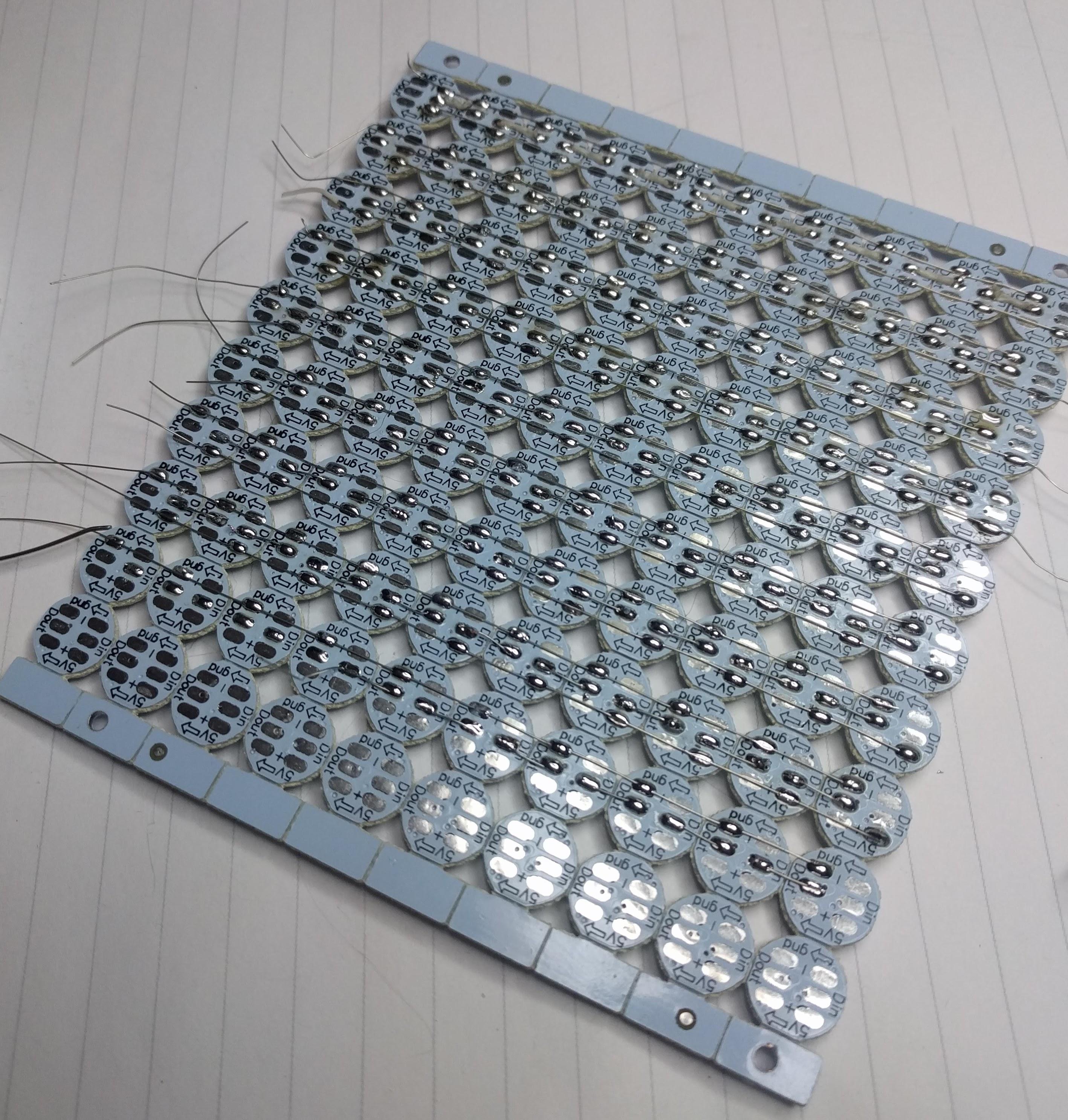
It took me the whole day to add those few wires and turn it into panel.

IMG_20200301_163206.jpg

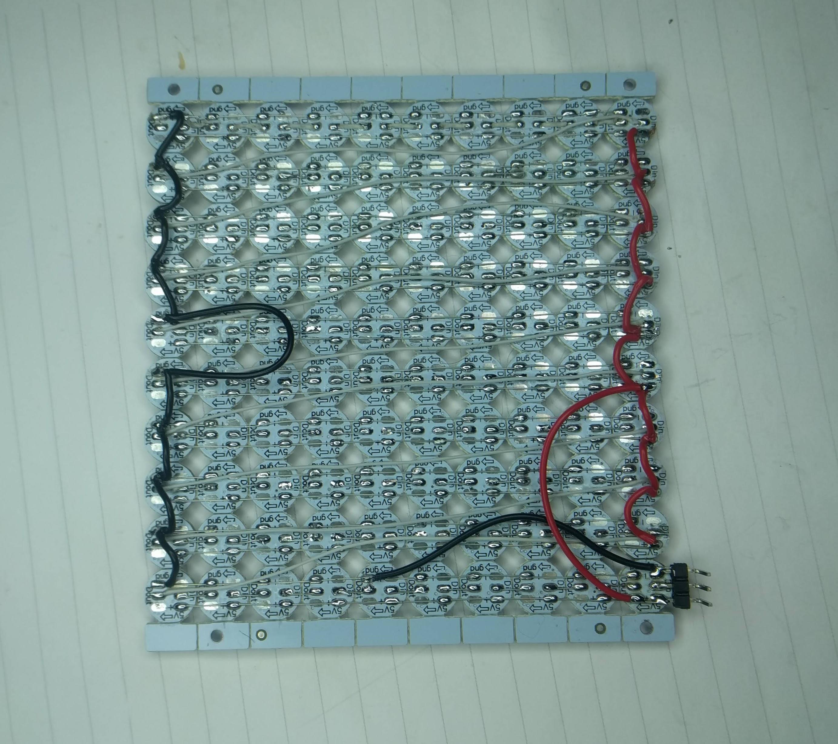
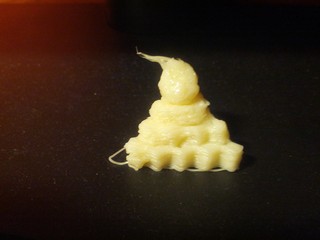
I started testing it using Arduino Nano with wrong FastLED example (which supports just 4 ws8212) and wondered why I'm not getting the whole panel to light up. After some sleep, I tried Adafruit example, fixed one broken data out-in wire in middle of panel and I got this:

Thumbnail image for IMG_20200302_105830.jpg

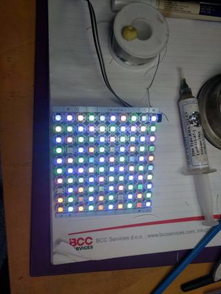
So, playing video on this panel should be easy now, right?

First, I had to make a choice of platform to drive the panel. While my 10x10 panel with 100 leds needed just 300 bytes for single frame, I didn't want to have a video sending device wired to it. So, esp8266 was logical choice to provide network connectivity to the panel without usb connection (which we still need, but just for power).

At first, I took the Lolin Node MCU clone, which doesn't have 5V broken out (why?), and its VIN pin has a diode between USB 5V pin and VIN, and diode voltage drop is enough to make ws2812 dark all the time.
Switching to Weemos D1 mini did help there, but what to run on it? I found some examples that where too clever for me (for 8x8 panel, they use jpeg and just decode single 8x8 block to show it which won't work for my 10x10 panel).
After a bit of googling, it seems to me that https://github.com/Aircoookie/WLED project is somewhat of Tasmota for WS2812 on ESP8266, so I decided to use it. While it's not designed to support WS2812 matrix but simple stripes, it has UDP realtime control which enables it to send 302 byte UDP packet (300 bytes of RGB data and two byte header).

So I started writing scripts which are at https://github.com/dpavlin/WLED-video to first convert video to raw frames using something as simple as ff2rgb.sh:

dpavlin@nuc:/nuc/esp8266/WLED-video$ cat ff2rgb.sh
#!/bin/sh -xe

f=$1

test ! -d $f.rgb && mkdir $f.rgb || rm -v $f.rgb/*.png
ffmpeg -i $f -vf scale=10x10 $f.rgb/%03d.png
ls $f.rgb/*.png | xargs -i convert {} -rotate 180 -gamma 0.3 -depth 8 {}.rgb
To send frames I wrote simple send.pl script. I would have loved to be able to use bash udp support or some standard utility (like netcat or socat) to send frames, but null values in data didn't work well with shell pipes and I wasn't able to make it work.
I also figured out that I have to modify gamma values for my frames so that colors are somewhat more correct (I had flame video which had blue hues on it without gamma correction). This is somewhat strange because WLED does have gamma correction for colors turned on, but it doesn't help and turning it off also doesn't help. So, gamma correction in pre-processing it is...

And since I already had perl script to send UDP packets, I decided to open ffmpeg from it and make single script ff2wled.pl which sends video to panel like this:

dpavlin@nuc:/nuc/esp8266/WLED-video$ ./ff2wled.pl rick.gif

rick-panel.gif

Was it all worth it? Honestly, no. The panel is small enough that video playback is really too much for such small resolution and it would be so much easier to buy ready-made panel with more leds. But, I did learn a few tricks with ffmpeg, and hopefully somebody else will benefit from this post.

This year on DORS/CLUC 2018 I decided to talk about device tree in Linux kernel, so here are blurb, presentation and video of that lecture.

You have one of those fruity *Pi arm boards and cheep sensor from China? Some buttons and LEDs? Do I really need to learn whole new scripting language and few web technologies to read my temperature, blink a led or toggle a relay?
No, because your Linux kernel already has drivers for them and all you need is device tree and cat.

hantek-dso-2090.jpg

I have been using Hantek DSO-2090 USB oscilloscope for more than half a year now. While scope purist will say that usb oscilloscopes are not good enough for serious use for my use it's quite sufficient. However, this weekend, I was reverse engineering CPLD with R2R digital to analog converter, and I needed to figure out which steps are produced by turning pins on CPLD on or off. Sure, I can use multi-meter to do this, but if I already have oscilloscope it's much more powerful tool for task like this.

When choosing USB oscilloscope, I searched a lot, and decided to buy Hantek DSO-2090 because it's supported by free software like OpenHantek and sigrok. There are better oscilloscopes out there, but this one is supported by free software, and there is even a detailed tear-down which explains how to increase it's performance. When scope arrived, I was quite pleased with OpenHantek, but never managed to get sigrok working with it. It didn't matter at the time, since OpenHantek had everything I needed. However, for this task at hand I really needed minimum and maximum voltage. As you can see in video describing oscilloscope usage, and especially Hantek DSO-2090, including it's limits.

openhantek.png

OpenHantek shows just amplitude of signal, which is difference between minimal and maximal voltage but doesn't show raw values which I needed. So, I wrote simple patch to OpenHantek to display minimum, amplitude and maximum voltage as you can see in picture. I also wrote a message on mailing list with a patch, so I hope you might expect to see this change in next version of OpenHantek.

When you are trying to configure touch screen on Linux machine, internet offers examples Xorg.conf configuration but without explanation were numbers in it came from. If you have different touch screen you might be out of luck or guess what to do. In this post, I will try to explain how to examine your device using evtest and try out settings using xinput without restarting X server or installing any drivers other than built-in evdev.

microtouch.jpg

We have a couple of 3M MicroTouch M150 touch screens which are VGA monitors (1024*768 resolution) with USB touchscreen interface which is reported as:

dpavlin@t42:~$ lsusb -d 0596:0001
Bus 002 Device 002: ID 0596:0001 MicroTouch Systems, Inc. Touchscreen
A bit of googling later, I found out that there are two different drivers for microtouch devices, but both of them support serial devices only. Not giving up that easily I decided to see what xinput reports about it (without any additional drivers installed!):
dpavlin@t42:~$ xinput list
⎡ Virtual core pointer                          id=2    [master pointer  (3)]
⎜   ↳ Virtual core XTEST pointer                id=4    [slave  pointer  (2)]
⎜   ↳ 3M 3M USB Touchscreen - EX II             id=9    [slave  pointer  (2)]
⎜   ↳ SynPS/2 Synaptics TouchPad                id=11   [slave  pointer  (2)]
⎜   ↳ TPPS/2 IBM TrackPoint                     id=12   [slave  pointer  (2)]
⎣ Virtual core keyboard                         id=3    [master keyboard (2)]
    ↳ Virtual core XTEST keyboard               id=5    [slave  keyboard (3)]
    ↳ Power Button                              id=6    [slave  keyboard (3)]
    ↳ Video Bus                                 id=7    [slave  keyboard (3)]
    ↳ Sleep Button                              id=8    [slave  keyboard (3)]
    ↳ AT Translated Set 2 keyboard              id=10   [slave  keyboard (3)]
    ↳ ThinkPad Extra Buttons                    id=13   [slave  keyboard (3)]
This seems like a good news, but when I tried to use it, it seemed that cursor would move only in middle of screen (with X axis swapped) so I wasn't very happy about it. Examining properties of device in more detail revealed that it has property to swap axes and calibrate them, but what to write into those values?
dpavlin@t42:~$ xinput list-props 9
Device '3M 3M USB Touchscreen - EX II':
        Device Enabled (139):   1
        Coordinate Transformation Matrix (141): 1.000000, 0.000000, 0.000000, 0.000000, 1.000000, 0.000000, 0.000000, 0.000000, 1.000000
        Device Accel Profile (263):     0
        Device Accel Constant Deceleration (264):       1.000000
        Device Accel Adaptive Deceleration (265):       1.000000
        Device Accel Velocity Scaling (266):    10.000000
        Device Product ID (257):        1430, 1
        Device Node (258):      "/dev/input/event7"
        Evdev Axis Inversion (267):     0, 0
        Evdev Axis Calibration (268):   <no items>
        Evdev Axes Swap (269):  0
        Axis Labels (270):      "Abs X" (261), "Abs Y" (262)
        Button Labels (271):    "Button Unknown" (260), "Button Unknown" (260), "Button Unknown" (260), "Button Wheel Up" (145), "Button Wheel Down" (146)
        Evdev Middle Button Emulation (272):    0
        Evdev Middle Button Timeout (273):      50
        Evdev Third Button Emulation (274):     0
        Evdev Third Button Emulation Timeout (275):     1000
        Evdev Third Button Emulation Button (276):      3
        Evdev Third Button Emulation Threshold (277):   20
        Evdev Wheel Emulation (278):    0
        Evdev Wheel Emulation Axes (279):       0, 0, 4, 5
        Evdev Wheel Emulation Inertia (280):    10
        Evdev Wheel Emulation Timeout (281):    200
        Evdev Wheel Emulation Button (282):     4
        Evdev Drag Lock Buttons (283):  0
First task was was to flip x axes to make it move left-right instead of right-left. This can be acomplised using following command:
dpavlin@t42:~$ xinput set-prop 9 267 1 0
Parameters are device id, property id, X axis swap and Y axis swap. If you don't know how many parameters property takes, just put one, try it out and if it returns errors, keep adding parameters until it suceeds.

Next, I needed to calibrate screen to track my finger moving over surface. This is where evtest comes into play. It's low level utility which enables you to see input events before they are passwd to Xorg server. You will have to run it as root as follows:

dpavlin@t42:~$ sudo evtest
No device specified, trying to scan all of /dev/input/event*
Available devices:
/dev/input/event0:      AT Translated Set 2 keyboard
/dev/input/event1:      Lid Switch
/dev/input/event2:      Sleep Button
/dev/input/event3:      Power Button
/dev/input/event4:      ThinkPad Extra Buttons
/dev/input/event5:      Video Bus
/dev/input/event6:      PC Speaker
/dev/input/event7:      3M 3M USB Touchscreen - EX II
/dev/input/event8:      SynPS/2 Synaptics TouchPad
/dev/input/event9:      TPPS/2 IBM TrackPoint
Select the device event number [0-9]: 7
Input driver version is 1.0.1
Input device ID: bus 0x3 vendor 0x596 product 0x1 version 0x410
Input device name: "3M 3M USB Touchscreen - EX II"
Supported events:
  Event type 0 (EV_SYN)
  Event type 1 (EV_KEY)
    Event code 330 (BTN_TOUCH)
  Event type 3 (EV_ABS)
    Event code 0 (ABS_X)
      Value   7353
      Min        0
      Max    16384
    Event code 1 (ABS_Y)
      Value   4717
      Min        0
      Max    16384
Properties:
Testing ... (interrupt to exit)
Immidiatly we can see minimum and maximum values for both axes and putting figer on top-left corner of screen produced (a lot of) output like this:
Event: time 1386078786.506710, -------------- SYN_REPORT ------------
Event: time 1386078786.510712, type 3 (EV_ABS), code 0 (ABS_X), value 13919
Event: time 1386078786.510712, type 3 (EV_ABS), code 1 (ABS_Y), value 2782
After a few touches I had coordinates which where something like this:
14046,27222380,2986
7994,7819
13743,136162624,13545
Strangly it seems that origin is top-right corner, but we shouldn't care much about it beacuse we can specify them using following command (after rounding them a bit):
dpavlin@t42:~$ xinput set-prop 9 268 2380 14000 2800 13500
Trying it out on screen proved that it now works as expected. Let's call this success and remember that current Xorg knows a lot of tricks itself (recognising USB touch devices is one of them).

As a side note you don't really need to use evtest to get device position. Using xinput list id syntax displays you more-or-less same information, including last point which you touched on device as seen below:

dpavlin@t42:~$ xinput list 9
3M 3M USB Touchscreen - EX II                   id=9    [slave  pointer  (2)]
        Reporting 3 classes:
                Class originated from: 9. Type: XIButtonClass
                Buttons supported: 5
                Button labels: "Button Unknown" "Button Unknown" "Button Unknown" "Button Wheel Up" "Button Wheel Down"
                Button state:
                Class originated from: 9. Type: XIValuatorClass
                Detail for Valuator 0:
                  Label: Abs X
                  Range: 0.000000 - 16384.000000
                  Resolution: 0 units/m
                  Mode: absolute
                  Current value: 13889.000000
                Class originated from: 9. Type: XIValuatorClass
                Detail for Valuator 1:
                  Label: Abs Y
                  Range: 0.000000 - 16384.000000
                  Resolution: 0 units/m
                  Mode: absolute
                  Current value: 2832.000000
However evtest will run in loop until you stop it with Ctrl+C so I find it a little bit easier to use than re-running xinput list id.

gnu-linux-on-arm-0.png Last week we had another annual conference about Free Software and Open Source DORS/CLUC 2013. For a last year, I was playing with various hardware, so this year, I was part of Internet of things panel (talking about ARM based machines), and I had lecture about GNU/Linux on ARM devices for $50-$100.

I also submitted hardware workshop for program which got accepted, so I quickly realized that I'm really no hardware expert and that I could use some help to make interesting workshop. Fortunately I have a few good friends who know more about hardware that I ever will, so I summoned Lovro and Dalibor to help me cover hardware and antenna design. Few weeks ago I was at NSND Belgrade 2013 where I had good fortune to meet Filip who is working for Dangerous Prototypes. I couldn't really believe my good luck since I wanted to talk about Bus Pirate a great multi-purpose tool which got me into hardware in the first place. So, in the end, I had three very skillful people to back me up in this workshop which was hopefully useful and interesting to people attending it. For future reference, I will include a few links below about topics we convered:

As you can see from notes above, workshop was a mix of different projects but hopefully it managed to convey my excitement about current moment in time where you can hack hardware even without taking soldering iron (and burning your fingers). If you do take soldering iron, please make your project Open Source Hardware...

usb-extesion-cable.jpg I recently got big screen TV (big for my living room at least). It came with few HDMI ports and VGA, so next logical step was to connect computer to it. And of course, then I noticed that it would be really handy to have wireless keyboard and mouse to complete this nice setup. However, I also wanted to ssh over that networks, so I started examining how secure wireless keyboards are. tl;dr; summary: they are not secure.

First I asked for suggestions which wireless keyboard to buy. I have quite big fingers, so mini models just doesn't do it for me. I got suggestion to take a look at Logitech K400 and sure enough it seemed like good choice. One of first things that I noticed is that it supports 128-bit AES encryption. I started to have a good feeling about it, but I wanted to know more, so I hoped to Logitech Advanced 2.4 GHz Technology pdf and discovered that not all keys are encrypted.To quote documentation:

The encryption applies to all standard keyboard keys (a, s, d, f...) and modifiers (Shift, Ctrl, Alt...). The multimedia keys (Play, Pause, Mute...) that may be implemented in some keyboards are transmitted in clear text.
How can I trust keyboard which doesn't encrypt all traffic? This got me thinking. Can I somehow verify that keys are encrypted? Is this wide-spread problem? Can I make mistake and broadcast my keystrokes to whole world?

Sure I can. For older 27Mhz keyboards there is KeyKeriki v1.0 - 27MHz project which implement sniffer for it (video DeepSec 2009: Keykeriki: Universal Wireless Keyboard Sniffing For The Masses). But, Logitech is 2.4Ghz, so it's secure, right? Well, there is KeyKeriki v2.0 - 2.4GHz which does same for 2.4Ghz (video Keykeriki V2 - Practical Exploitation of Modern Wireless Devices [SIGINT10]). OK, Logitech does some kind of AES on top of that, but since it does transfer some keys unencrypted, and it's proprietary technology I can't really check that.

I also got suggestion to use bluetooth keyboard because it's secure. Well, quick search revealed Ubertooth One which basically defeats bluetooth protection with a bit of sniffing and a little brute force.

By this point, I was puzzled. Is there secure wireless keyboard with touchpad which I can buy? Something I can be sure that it encrypts all traffic as opposed to only some keys? Or is usb extension cable only real solution for me?

Allmost a year ago, me and three other friends decided it's a very good idea to support Printrbot kickstarter project and get our-selfs 3D printer. We didn't have any particular use for it (other than printing Raspberry Pi case when it arrives) but it seemed like the right thing to do. This post will try to explain how far did we manage to get with it and why we where wrong.

If you examine original Kickstarter page you will see following description:

A desktop 3D printer you can build in a couple hours. Print plastic parts you design or download - even parts for another printer.
Our experience can't be further from that statement. For a start, Brook Drumm (to whom I'm ethereally grateful for his efforts to make 3D printers commonplace) got his campaign funded with 1,808 backers who spent $830,827 instead of just $25,000 goal he envisioned. This was both good and bad. Good part was that after funding we knew that we will have 3D printer (I'm carefully not mentioning printing anything), but the bad part was logistics: there was simply no way he would be able to print 1808 versions of original design on 3D printers themselves (idea of RapRap-like printers, which Printrbot was one iteration, was always to make them self-replicating). So, he decided to change design and move toward wooden laster-cut parts for most of construction, and print just parts which where necessary.

This also introduced significant delay in printer shipment, but when you are funding Kickstarter project, you should be prepared for it, so I'm not complaining. When it finally arrived this summer (10 months after end of Kickstarter campaign), it was significantly bigger than I expected:

IMG_20120907_174405.jpg

To be honest, we did upgrade to bigger Printrbot PLUS so I guess we should expect a lot of parts. As we are mostly software geeks, we did only reasonable thing to do: check if all parts are present comparing it with bill of materials which we got printed out.

IMG_20120907_183819.jpg IMG_20120907_183833.jpg IMG_20120907_185152.jpg

This is the point where our problems started. We had missing one bag of parts which included termistor and switches. We contacted Printrbot HQ and they sent us missing parts. We started assembling following Printrbot Building Instructions by Brook Drumm and it took us more than 50 hours to get to our first blob.

IMG_20121019_232542.jpg

Of course, it didn't work perfectly on first run. We where trying to print 5mm Calibration Cube Steps is ABS plastic which we received with our Printrbot (we even got additional 450g of ABS plastic as replacement for power supply which wasn't part of international shipments).

5mm_Cal_Cubes.jpg

Actually, it still doesn't work well as you can see in video below, but we are hopeful. In the meantime we figure out that best source of information is Printrbot Talk forum and wiki. Forum is somewhat depressive since most users have some kind of problems with their built, just as we do.

To be honest, we didn't expect smooth ride. However, as I mentioned before we are not really hardware hackers, and my only conclusion is that home-made 3D printers are really for people who already have enough experience to make their own 3D printer, and not for software guys like us. However, we won't give up, and I fully expect to have working printer (after we get replacement barrings from Printrbot HQ because our are sticky). We are collecting useful add-on models and instructions on our Printrbot wiki page but I didn't expect that we will have to contact Printrbot HQ twice for missing and replacement parts. But eventually we will be able to print Raspberry Pi box, I hope :-)

Nook Color X11 frame buffer.jpg I have been toying around with idea of having real Linux stack (X11 and friends) on Nook Color. While this seems like a silly thing to do, it does allow me to use x2x and transfer keyboard and mouse from my laptop to tablet which is handy. If also allows me to run X11 applications on tablet screen using DISPLAY=nook.lan:0. I was fortunate enough to find blog post how to run Linux framebuffer X server on Android but I wanted to use touchscreen so I decided to write my own xorg.conf (this brings back memories...).

To get full-blown Debian-based distribution on your Android take a look at BotBrew Basil. It's Emdebian based distribution which will setup mount points and various other stuff so you don't have to do that manually. Since it's Debian based, you are not limited to Emdebian packages -- you can (and will have to) add normal sid:

(BotBrew)root@localhost:/# cat /etc/apt/sources.list.d/sid.list 
deb [arch=armel] http://ftp.debian.org/debian sid main contrib non-free
If you want to know more about Emdebian hop over to DebConf 12: Integrating Emdebian into Debian [video].

With all this prepared, we are ready to shut down Android stack:

adb shell setprop ctl.stop media
adb shell setprop ctl.stop zygote
adb shell setprop ctl.stop surfaceflinger
adb shell setprop ctl.stop drm
Next step is installation of required packages:
dpavlin@t61p:~$ adb shell
root@android:/ # TERM=xterm chroot /data/botbrew-basil/ /bin/bash --login
(BotBrew)root@localhost:/# apt-get install xserver-xorg-video-fbdev xserver-xorg-input-evdev \
   xserver-xorg-input-multitouch x11-xserver-utils xinit \
   matchbox matchbox-keyboard xterm
I decided to use matchbox, mostly becuase it's only window manager which comes with on-screen keyboard which is useful on touch screen device.

After installation you will need to setup X symlink and create .xinitrc:

root@android:/ # ln -s /usr/bin/Xorg /usr/bin/X

root@android:/ # cat ~/.xinitrc                                              
( sleep 1 ; matchbox-keyboard -o portrait ) &
xhost 192.168.1.61
matchbox-session
Finally, you need to create xorg.conf:
Section "ServerLayout"
    Identifier    "Layout0"
    Screen        "Screen0"
    InputDevice   "cyttsp-i2c" "CorePointer"
    InputDevice   "gpio-keys" "CoreKeyboard"
    InputDevice   "twl4030-keypad" "CoreKeyboard"
EndSection

Section "InputDevice"
    Identifier    "gpio-keys"
    Driver        "evdev"
    Option        "Device" "/dev/input/event0"
    # code 102 (KEY_HOME)
    # code 116 (KEY_POWER)
EndSection

Section "InputDevice"
    Identifier     "twl4030-keypad"
    Driver         "evdev"
    Option         "Device" "/dev/input/event1"
    # code 114 (KEY_VOLUMEDOWN)
    # code 115 (KEY_VOLUMEUP)
EndSection

Section "InputDevice"
    Identifier     "cyttsp-i2c"
    Driver         "multitouch"
    Option         "Device" "/dev/input/event2"
    # mouse should move as fast as finger and not faster
    Option         "AccelerationScheme" "none"
    # evdev has it, multitouch doesn't so it behaves like touchpad
#   Option         "IgnoreRelativeAxes" "True"
EndSection

Section "Device"
    Identifier    "Card0"
    Driver        "fbdev"
    Option        "fbdev" "/dev/graphics/fb0"
    # rotate screen to be in sync with touchpad orientation
    Option        "Rotate" "CCW" # CW=90 UD=180 CCW=270
EndSection

Section "Screen"
    Identifier    "Screen0"
    Device        "Card0"
EndSection
This will map all hardware keys and use mutitouch driver for screen. To make it work, I used evtest package which allows you to see events from input devices so you will know which device produce keyboard events and which produce multitouch events. To be honest, this solution isn't prefect, because screen behaves like touchpad, so you can't just point to screen and expect your cursor to just to that position.

Following video shows X server in action.

This is simple unaccelerated frame buffer. This makes performance less then desirable. There are a few implementations of OMAP xorg server:

  • xf86-video-omapfb uses DSS kernel support which seems to be part of CM kernel, so this might be good next thing to try out
  • xf86-video-omap is newer implementation, but this requires 3.3 kernel and is not yet stable.
Having accelerated OMAP X server and fixed touchscreen issues would make Nook somewhat nice Linux tablet, if only it isn't so heavy for day-to-day use :-)